Magnetic sensor and production method thereof

a technology of magnetic sensors and production methods, applied in the field of magnetic sensors, can solve the problems of difficult to improve the accuracy of perpendicularity, difficult to connect electric wiring, and large three-axis direction sensor size, so as to reduce the number of fabrication steps, improve fabrication yield, and reduce the effect of manufacturing steps

Inactive Publication Date: 2009-01-15
RICOH KK
View PDF6 Cites 38 Cited by
  • Summary
  • Abstract
  • Description
  • Claims
  • Application Information

AI Technical Summary

Benefits of technology

[0057]each of the fixed resistors includes a magneto-resistance effect element formed from the same layer configuration as the magnetic field detectors.
[0058]According to the above embodiments of the present invention, since the magnetic field detectors in the sensor bridge circuits are arranged on the inclined surfaces which have normal directions intersecting with each other in a three-dimensional manner, and the pair of the magnetic field detectors in the same sensor bridge circuits is arranged in the same inclined surface, by applying a magnetic field in one direction while heating the substrate in the magnetic field only once, it is possible to magnetize the pinned layers of the magnetic field detectors in one direction, and it is possible to realize magnetization in three magnetization directions, in which magnetization directions of the pinned layers in different coordinate systems intersect with each other in a three-dimensional manner. As a result, it is possible to reduce the number of fabrication steps, and improve fabrication yields. In addition, since the integration mounting on the substrate is possible, the magnetic sensor can be made small and thin, and a large number of the magnetic sensors can be fabricated; that is, productivity is improved.

Problems solved by technology

However, in the three-axis direction sensor disclosed in reference 2, because of the three-dimensional mounting, it is difficult to improve precision of the perpendicularity of the three axes, interconnection of electric wiring is complicated, and the three-axis direction sensor becomes relatively large.
In addition, in order to bend and fix the flexible substrate, a certain overlap width is required, and this results in a thick and large substrate member for fixing the flexible substrate.
Uncertainty of the precision of the relative position between the three axes results in inclination of the position precision obtained from the measured output of the external magnetic field.
In addition, when installing the three-axis direction sensor in a mobile phone or other devices, small and thin magnetic sensors are required.
However, the three-axis direction sensors disclosed in reference 2 and reference 3 have limitations in this aspect.

Method used


Image

  • Magnetic sensor and production method thereof
  • Magnetic sensor and production method thereof
  • Magnetic sensor and production method thereof

Examples


embodiment 1

[0106]In this embodiment, magnetic field detectors are arranged in the same inclined surface having a certain angle.

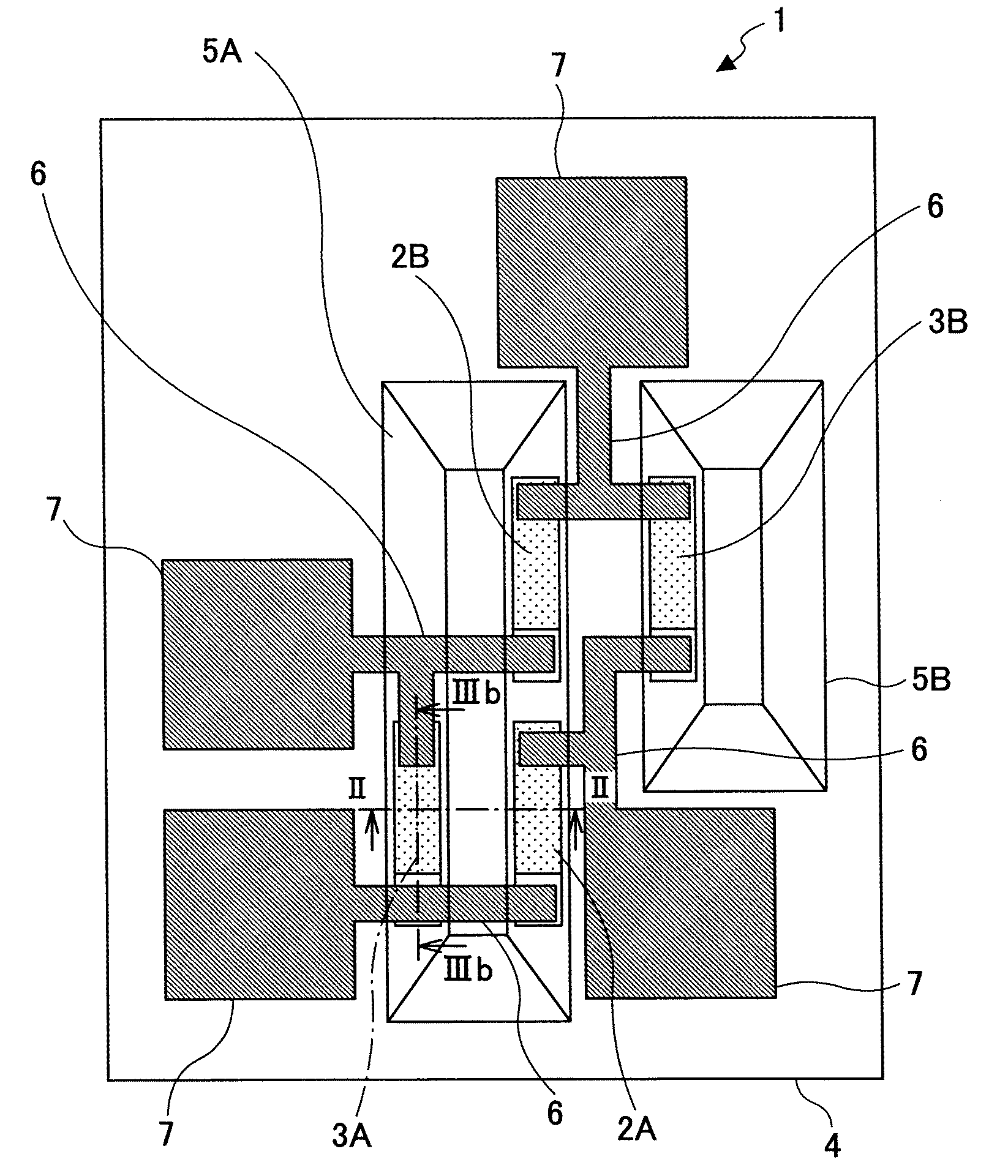
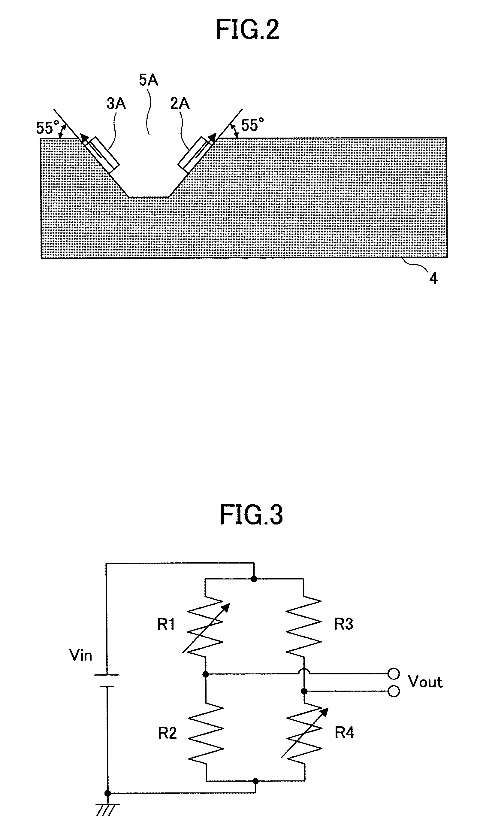
[0107]FIG. 1 is a plan view schematically illustrating a configuration of a magnetic sensor according to a first embodiment, in which magneto-resistance effect elements are connected to form a bridge circuit.

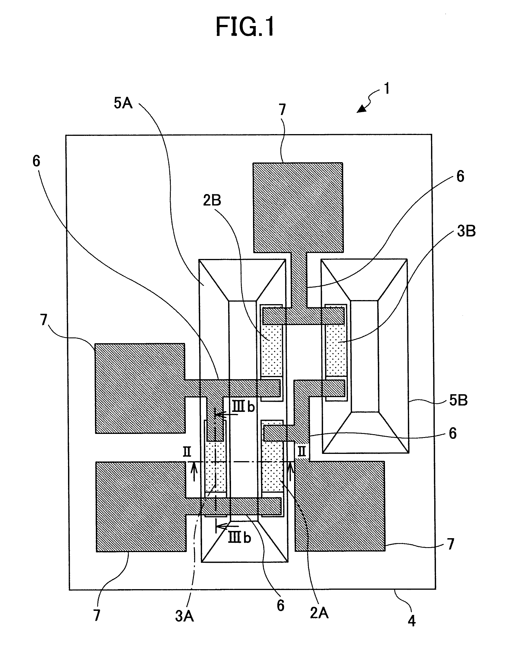
[0108]As shown in FIG. 1, a magnetic sensor 1 of the present embodiment includes a substrate 4, a magnetic field detector 2A, a magnetic field detector 2B, a fixed resistor 3A, a fixed resistor 3B arranged on the substrate 4, grooves 5A, 5B (collectively referred to as “grooves 5” where necessary), connection wirings 6, and bonding pads 7.

[0109]For example, the magnetic field detectors 2A, 2B, the fixed resistors 3A, 3B are Tunnel Magneto-Resistive (TMR) elements. In addition, the magnetic field detectors 2A, 2B, and the fixed resistors 3A, 3B have the same layer configuration. In each of the fixed resistors 3A, 3B, a magnetic shielding film is provided to reduce s...

embodiment 2

[0147]Similar to the first embodiment, in this embodiment, magnetic field detectors are arranged in the same inclined surface having a certain angle.

[0148]FIG. 6 is a plan view schematically illustrating a configuration of a magnetic sensor according to a second embodiment, in which magneto-resistance effect elements are connected to form a bridge circuit.

[0149]As shown in FIG. 1, a magnetic sensor 301 of the present embodiment includes a substrate 304, a magnetic field detector 302A, a magnetic field detector 302B, a fixed resistor 303A, a fixed resistor 303B arranged on the substrate 304, a groove 305, connection wirings 306, and bonding pads 307.

[0150]In the magnetic sensor 301, the fixed resistor 303A and the fixed resistor 303B are arranged on the same surface where the bonding pads 307 are formed.

[0151]Here, for example, the magnetic field detectors 302A, 302B, the fixed resistors 303A, 303B are Tunnel Magneto-Resistive (TMR) elements, and have the same layer configuration. In...

embodiment 3

[0166]In this embodiment, magnetic field detectors and fixed resistors are arranged in inclined surfaces of the same groove.

[0167]FIG. 8 is a plan view schematically illustrating a configuration of a magnetic sensor according to a third embodiment, in which magneto-resistance effect elements are connected to form a bridge circuit.

[0168]FIG. 9 is a cross-sectional view along a XVII-XVII line in FIG. 8.

[0169]As shown in FIG. 8, a magnetic sensor 401 of the present embodiment includes a substrate 404, a magnetic field detector 402A, a magnetic field detector 402B, a fixed resistor 403A, a fixed resistor 403B arranged on the substrate 404, a groove 405, connection wirings 406, and bonding pads 407.

[0170]In the magnetic sensor 401, the magnetic field detector 402A, the magnetic field detector 402B, the fixed resistor 403A, and the fixed resistor 403B are arranged in the inclined surfaces of the same groove 405.

[0171]Here, for example, the magnetic field detectors 402A, 402B, the fixed re...


PUM

PropertyMeasurementUnit
angleaaaaaaaaaa
depthaaaaaaaaaa
depthaaaaaaaaaa

Abstract

A magnetic sensor is disclosed that has plural axes at the same time, able to be fabricated in a small number of steps. The magnetic sensor includes a substrate; and plural sensor bridge circuits each including a pair of magnetic field detectors and a pair of fixed resistors on the substrate, the pair of the magnetic field detectors and the pair of the fixed resistors being connected to form a bridge circuit, each of the magnetic field detectors being formed of a magneto-resistance effect element, and magnetization directions of the magnetic field detectors intersect with each other in a three-dimensional manner. The substrate has plural inclined surfaces, normal directions of the inclined surfaces intersect with each other in a three-dimensional manner, and the pair of the magnetic field detectors in each of the sensor bridge circuits is arranged on the same inclined surface.

Description

BACKGROUND OF THE INVENTION[0001]1. Field of the Invention[0002]The present invention relates to a magnetic sensor using a magneto-resistance element, and a method of producing the magnetic sensor.[0003]2. Description of the Related Art[0004]In the related art, there are various kinds of sensors having magneto-resistance elements, and such kind of sensors include those using a magneto-resistance effect element (MR element), a magneto-impedance element (MI element), a fluxgate sensor, a semiconductor Hall effect sensor, and others.[0005]For example, consider an MI sensor, since an MI element (a magneto-resistance element) is used, it is easy to make the MI sensor thin and small, and further improvement is being made.[0006]As for an MR element, when a high-frequency current flow in the MR element, a high-frequency impedance of the MR element changes along with a magnetic field, and it is possible to detect the field strength of the magnetic field by utilizing the change of the high-fr...

Claims


Application Information

Patent Timeline
Patent Type & Authority Applications(United States)
IPC IPC(8): G01R33/09G01R3/00
CPCB82Y25/00Y10T29/49002G01R33/093
Inventor AZUMI, JUNICHIKOU, FUTOYOSHIFUSE, AKIHIRO
Owner RICOH KK
Why Eureka
Try Eureka