Electronic device and short-circuited dipole antenna thereof
a dipole antenna and electronic device technology, applied in the direction of antennas with plural divergent straight elements, antenna feed intermediates, antennas, etc., can solve the problems of external antenna devices deteriorating the appearance of wireless printers, etc., to achieve low production cost, simple structure, and easy manufacturing process
- Summary
- Abstract
- Description
- Claims
- Application Information
AI Technical Summary
Benefits of technology
Problems solved by technology
Method used
Image

Examples
embodiment one
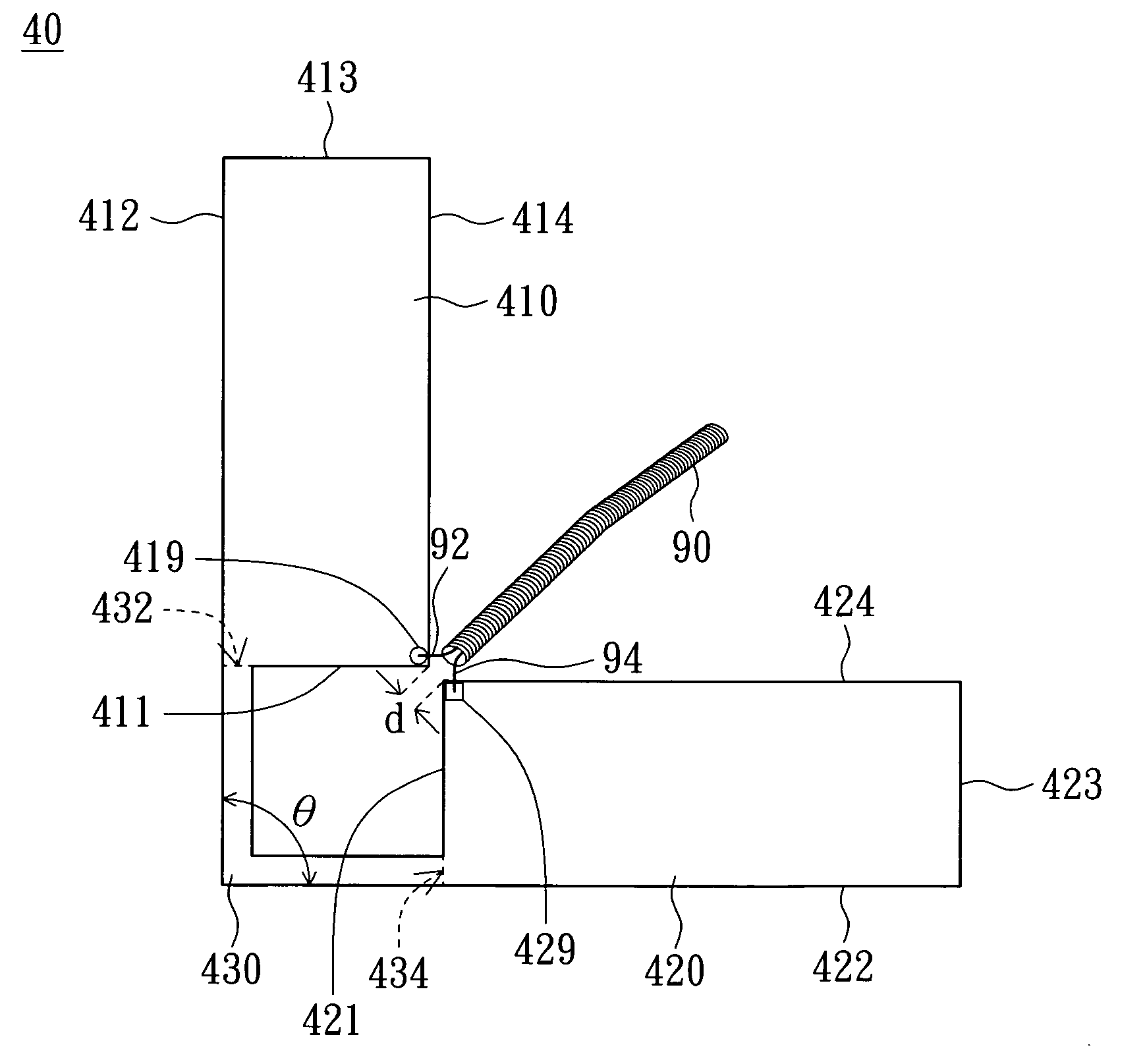
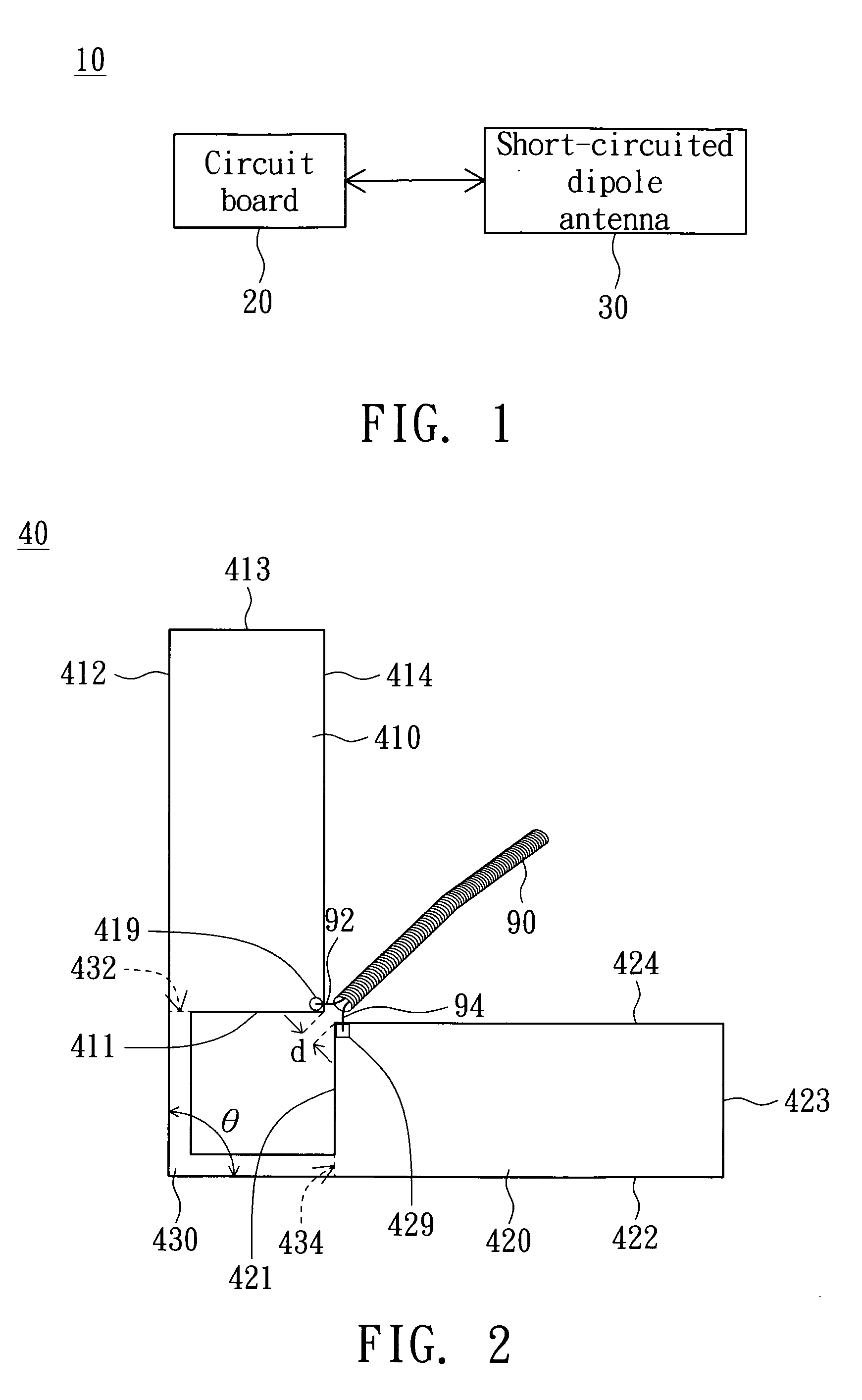
[0028]Referring to FIG. 2, a schematic diagram of a short-circuited dipole antenna according to a first embodiment of the invention is shown. The short-circuited dipole antenna 30 is the short-circuited dipole antenna 40 of FIG. 2 for instance, and the short-circuited dipole antenna 40 includes radiation units 410 and 420 and a short-circuited unit 430. For example, the radiation units 410 and 420 and the short-circuited unit 430 are manufactured into a unity and formed on a dielectric substrate by printing or etching. Besides, the radiation units 410 and 420 and the short-circuited unit 430 can also be formed by cutting metal sheets.
[0029]The short-circuited dipole antenna 40 not only has a simple structure but also has a low production cost when the radiation units 410 and 420 and the short-circuited unit 430 are manufactured into a unity. Besides, owing to that the radiation units 410 and 420 and the short-circuited unit 430 are manufactured into a unity, no extra plastic support...
embodiment two
[0038]Referring to FIG. 6, a schematic diagram of a short-circuited dipole antenna according to a second embodiment of the invention is shown. The difference between the first embodiment and the second embodiment lies on that the radiation units 510 and 520 of the second embodiment have different shapes from the radiation units 410 and 420 of the first embodiment.
[0039]The radiation unit 510 includes sides 511, 512, 513, 514, 515 and 516. For example, the side 513 is longer than the side 511, and the side 511 is longer than the side 515. The sides 511 and 513 of the radiation unit 510 are substantially in parallel to the side 515, while the sides 512 and 514 of the radiation 510 are substantially in parallel to the side 516. The sides 511, 513 and 515 are substantially vertical to the sides 512, 514 and 516 respectively to form an L shape.
[0040]Similarly, the radiation unit 520 includes sides 521, 522, 523, 524, 525 and 526. For example, the side 523 is longer than the side 521, and...
embodiment three
[0041]Referring to FIG. 7, a schematic diagram of a short-circuited dipole antenna according to a third embodiment of the invention is shown. The difference between the third embodiment and the first embodiment lies on that the radiation units 610 and 620 of the third embodiment have different shapes from the radiation units 410 and 420 of the first embodiment.
[0042]The radiation unit 610 includes sides 611, 612, and 613. For example, the side 613 is longer than the side 612, and the side 612 is longer than the side 611. The sides 611 and 612 are substantially vertical to each other, and the sides 611, 612 and 613 form a triangle.
[0043]Similarly, the radiation unit 620 includes sides 621, 622, and 623. For example, the side 623 is longer than the side 622, and the side 622 is longer than the side 621. The sides 621 and 622 are substantially vertical to each other, and the sides 621, 622 and 623 form another triangle.
PUM
 Abstract
Description
Claims
Application Information
 - R&D Engineer
- R&D Manager
- IP Professional
- Industry Leading Data Capabilities
- Powerful AI technology
- Patent DNA Extraction
Browse by: Latest US Patents, China's latest patents, Technical Efficacy Thesaurus, Application Domain, Technology Topic.
© 2024 PatSnap. All rights reserved.Legal|Privacy policy|Modern Slavery Act Transparency Statement|Sitemap