Display device and driving circuit thereof

a technology of driving circuit and display device, which is applied in the direction of illuminated signs, display means, instruments, etc., can solve the problems of ineffective overdrive technique, and achieve the effect of low cost, high speed, and high speed

Inactive Publication Date: 2009-01-15
RENESAS ELECTRONICS CORP
View PDF7 Cites 78 Cited by
  • Summary
  • Abstract
  • Description
  • Claims
  • Application Information

AI Technical Summary

Benefits of technology

[0008]In view of these circumstances, the present invention has been made and an object thereof is to provide a technique which can respond at a sufficient high speed according to element characteristic and a tempe

Problems solved by technology

As described above, there is a case that

Method used


Image

  • Display device and driving circuit thereof
  • Display device and driving circuit thereof
  • Display device and driving circuit thereof

Examples


first embodiment

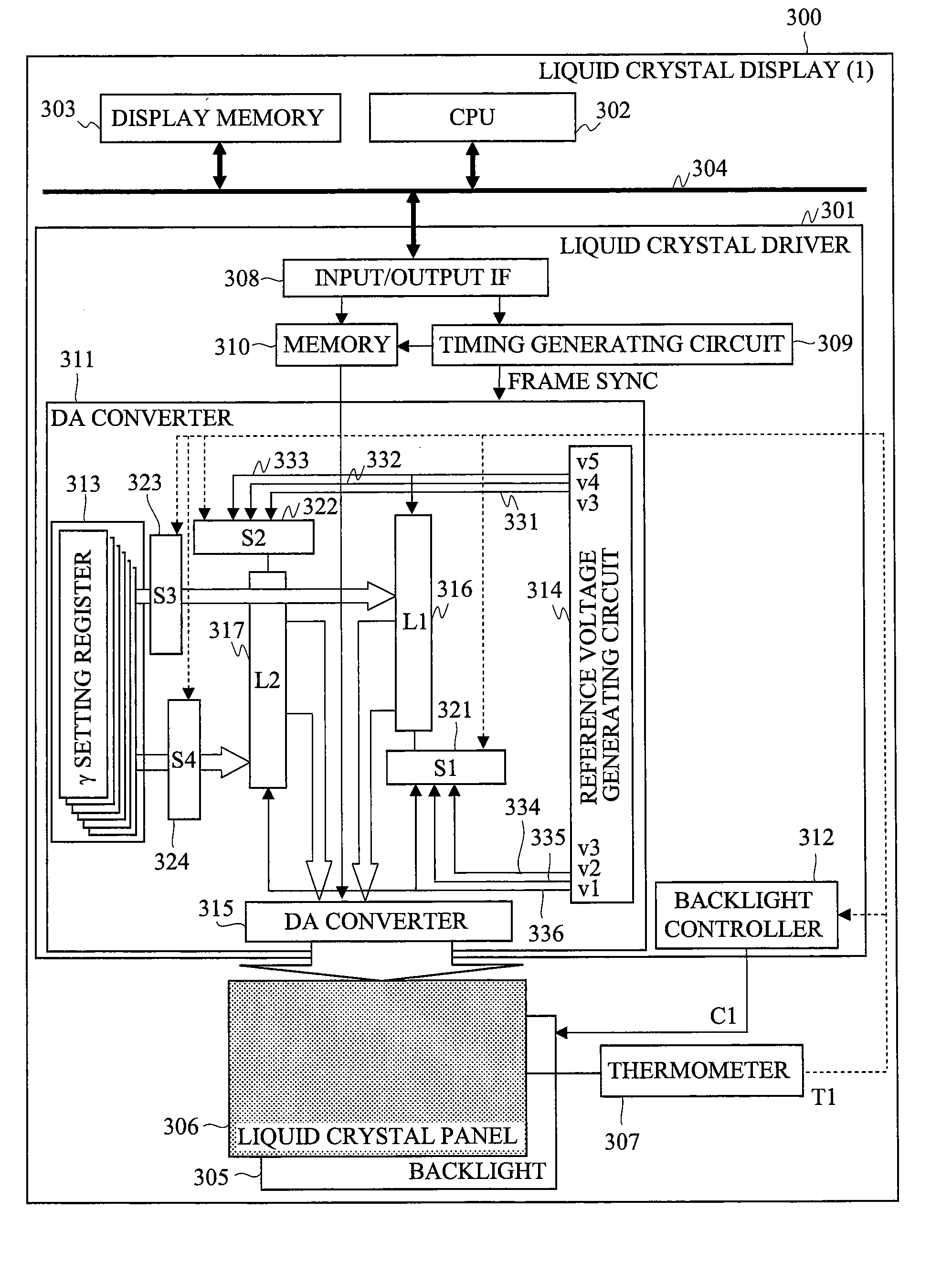
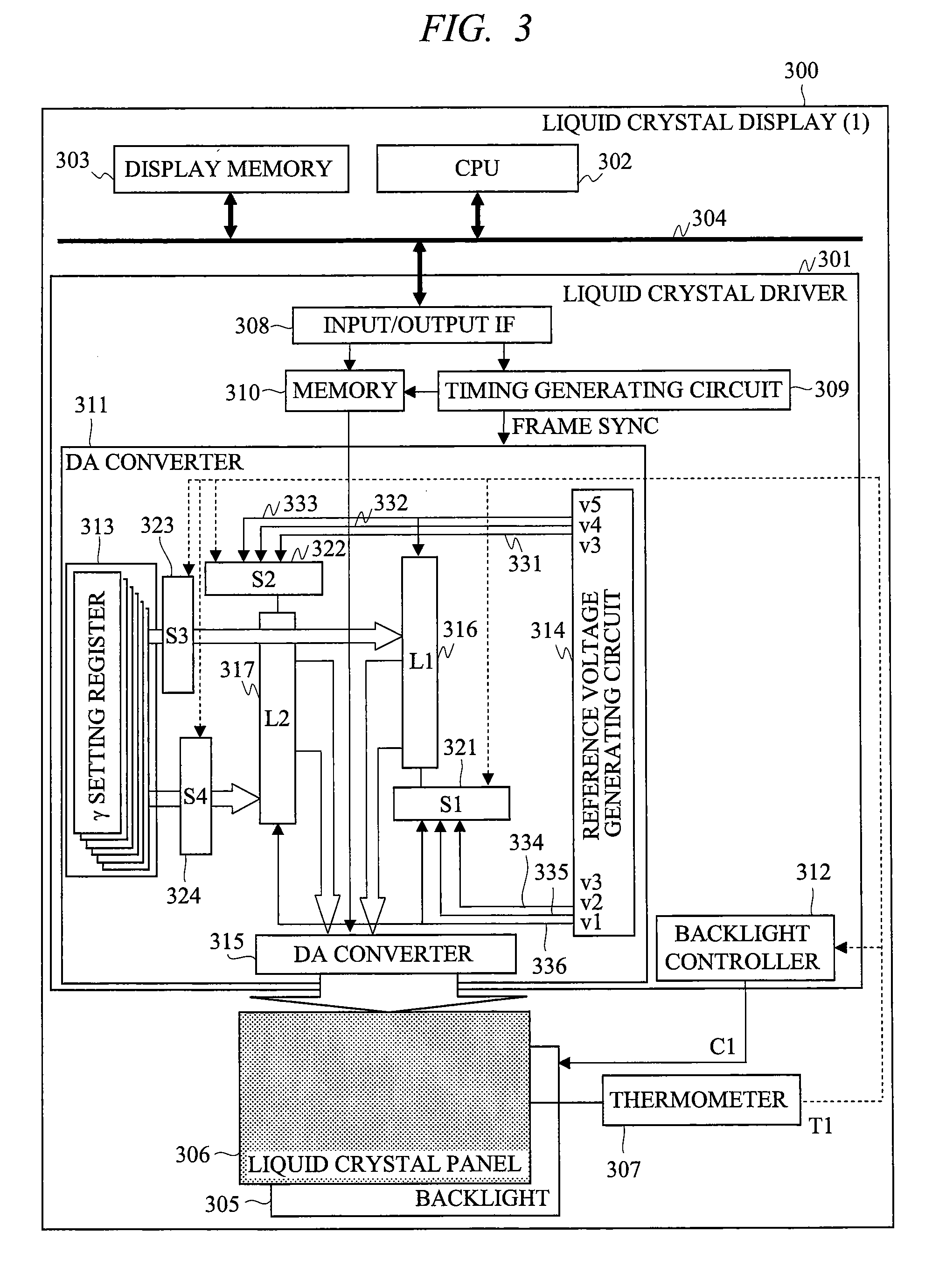
[0052]In view of the above circumstances, a display device (liquid crystal display) and a driving circuit (liquid crystal driver) of the same according to a first embodiment of the present invention will be explained with reference to FIG. 1 to FIG. 6. In the first embodiment, display data compression and control of a backlight light amount corresponding to liquid crystal characteristic and a temperature state are performed as a characteristic system in the present invention, and they are realized especially by configurations of a DA converting section 311 and a backlight controller 312 within a liquid crystal driver 301 shown in FIG. 3. In the above control, a grayscale range of display data is compressed to a low grayscale side (range change) at a low temperature time and a light amount of backlight is increased in correlation with an amount of lowered luminance due to the compression so that the luminance is caused to approach the original luminance.

[0053]

[0054]First, referring t...

second embodiment

[0098]Next, a liquid crystal display and a liquid crystal driver according to a second embodiment of the present invention will be explained with reference to FIGS. 7 and 8. In the second embodiment, a basic operation thereof is similar to that of the first embodiment, but a feature of the second embodiment lies in a configuration where both an overdrive function and a characteristic system in the present invention are used, and the second embodiment is different in a circuit system regarding a display data compression processing from the first embodiment. In the second embodiment, regarding a grayscale compression processing, grayscale voltages of the number more than the number of grayscales are produced in a configuration where the grayscale voltage generating circuit (ladder circuit) is sub-divided and an output grayscale voltage is selected from the grayscale voltages produced.

[0099]FIG. 7 shows a block configuration of a liquid crystal display 300 according to the second embod...

third embodiment

[0109]Next, a liquid crystal display and a liquid crystal driver according to a third embodiment of the present invention will be explained with reference to FIG. 9. A feature of the third embodiment lies in a system of a digital processing where a display data compression processing is performed as the grayscale value remains. In the third embodiment, an overdrive factor (grayscale value K) is calculated by an overdrive factor operating circuit 702. The liquid crystal driver 301 is provided with a data compression factor output circuit 801 and compression operating circuits 802 and 803, and the data compression factor output circuit 801 outputs a fixed value as data compression factor β(β=1−α) based upon the temperature information (T1) provided from the thermometer 307. The data compression factor β is outputted to the compression operating circuits 802, 803 and a backlight controller 312.

[0110]For example, when control is performed at the compression ratio α shown in FIG. 4, as t...


PUM


Abstract

In a display device such as a liquid crystal display, a processing for compressing a range of display data (grayscale) to a low grayscale side (a grayscale range where response is fast) except for a high grayscale side (a grayscale range where response is slow) at a predetermined compression ratio to conduct display according to response characteristic of transition between grayscales and a temperature state and a processing for increasing a light amount of a backlight to compensate for luminance change due to the compression are performed, for example, in a liquid crystal panel of TN liquid crystal. Thereby, response can be made fast even at a low temperature time.

Description

CROSS-REFERENCE TO RELATED APPLICATION[0001]The present application claims priority from Japanese Patent Application No. JP 2007-183299 filed on Jul. 12, 2007, the content of which is hereby incorporated by reference into this application.TECHNICAL FIELD OF THE INVENTION[0002]The present invention relates to a display device which is provided with a light source whose light amount can be controlled and conducts display by controlling a transmissivity control element which is disposed on a front face side of the light source and can control a light transmissivity and a driving circuit of the same, and in particular to a liquid crystal display device (a liquid crystal display) provided with a liquid crystal element (a liquid crystal panel) and a driving circuit (an LSI or the like) thereof.BACKGROUND OF THE INVENTION[0003]As a display device provided with a light source and a transmissivity control element, there is a liquid crystal display provided with a backlight and a liquid cryst...

Claims


Application Information

Patent Timeline
IPC IPC(8): G09G3/36
CPCG09G3/3406G09G3/3611G09G3/3688G09G3/3696G09G2310/027G09G2360/18G09G2320/0271G09G2320/041G09G2320/0646G09G2320/0673G09G2340/16G09G2320/0252G02F1/133G09G3/20G09G3/34G09G3/36
Inventor KATAYAMA, YUKARIKUROKAWA, YOSHIKIAKAI, AKIHITOSAKAMAKI, GORO
Owner RENESAS ELECTRONICS CORP
Why Eureka
Try Eureka