Liquid ejection control apparatus, liquid ejection control method and liquid ejection apparatus

a control apparatus and liquid ejection technology, applied in the direction of printing, other printing apparatus, etc., can solve the problems of large volume of data required for correction, high complexity of the system for performing correction, and non-uniform density, and achieve good liquid ejection results

Inactive Publication Date: 2009-01-15
SEIKO EPSON CORP
View PDF6 Cites 21 Cited by
  • Summary
  • Abstract
  • Description
  • Claims
  • Application Information

AI Technical Summary

Benefits of technology

[0008]An advantage of some aspects of the present invention is to provide a liquid ejection control apparatus, a liquid ejection control method and a liquid ejection apparatus, whereby good liquid eje

Problems solved by technology

Fluctuation in the ink ejection characteristics is a cause of density non-uniformities in the lines corresponding to the respective nozzles, in the print result.
Therefore, in order to obtain good print results at all times, using a printer having nozzle rows arranged in multiple layers, the volume of data required for correction becomes very large, and there is a

Method used


Image

  • Liquid ejection control apparatus, liquid ejection control method and liquid ejection apparatus
  • Liquid ejection control apparatus, liquid ejection control method and liquid ejection apparatus
  • Liquid ejection control apparatus, liquid ejection control method and liquid ejection apparatus

Examples


modification examples

[0045]5. Modification examples

[0046]6. Summary

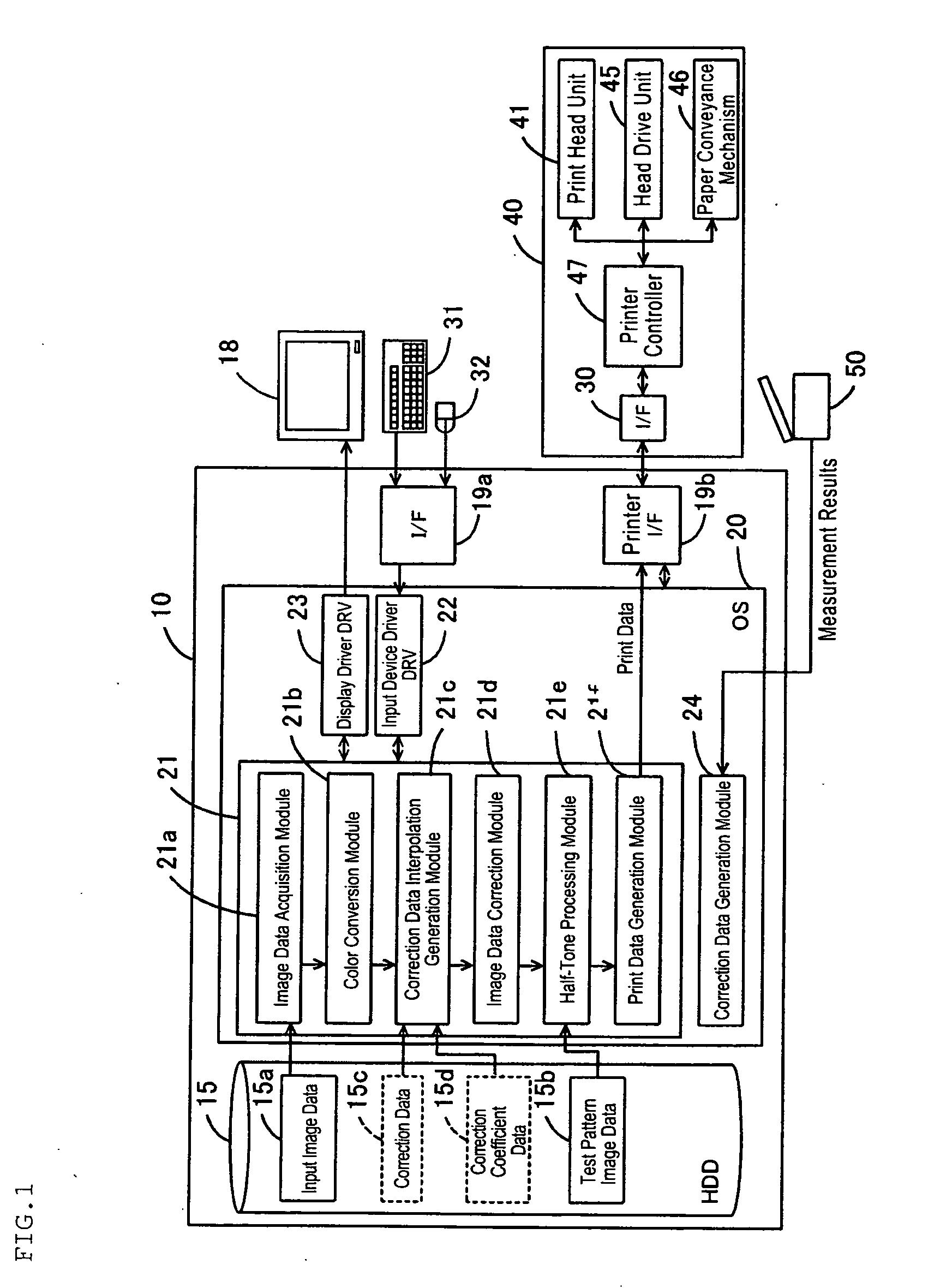
[0047]1. General Composition of Apparatus

[0048]FIG. 1 shows the general composition of a computer, and the like, which relates to the present embodiment. The computer 10 comprises a CPU (not shown) which forms a kernel for calculation processing, a ROM forming a storage medium, a RAM, and the like, and it executes a prescribed program while using peripheral devices, such as the HDD 15. A printer 40 which forms a printing apparatus is connected to the computer 10 via a printer interface 19b (for example, a serial interface). Apart from this, the computer 10 is also connected via an interface 19a to operating input devices, such as a keyboard 31, a mouse 32, or the like, and furthermore, it is also connected to a display monitor 18 via a video board, which is not shown. The computer 10 is the main control apparatus for the printer 40, and it forms a liquid ejection control apparatus. Furthermore, the computer 10, the printer 40, and other ...


PUM


Abstract

A liquid ejection control apparatus which controls a liquid ejection mechanism having a plurality of nozzle groups made up of a plurality of nozzles for ejecting liquid, comprising: a usage ratio determination unit which determines a usage ratio between the plurality of nozzle groups when performing liquid ejection; a correction data generation unit which generates correction data corresponding to the determined usage ratio, by using respective correction data for correcting density of liquid ejection results corresponding respectively to a plurality of usage ratios between the nozzle groups; an image data correction unit which corrects prescribed image data on the basis of the generated correction data; and an ejection execution control unit which executes liquid ejection by driving the respective nozzle groups on the basis of the corrected image data and the determined usage ratio.

Description

[0001]The entire disclosure of Japanese Patent Application No. 2007-184649, filed Jul. 13, 2007, is expressly incorporated by reference herein.BACKGROUND OF THE INVENTION[0002]1. Technical field[0003]The present invention relates to a liquid ejection control apparatus, a liquid ejection control method and a liquid ejection apparatus.[0004]2. Related Art[0005]There are printers which carry out printing by forming a plurality of nozzles for ejecting ink, in which nozzle rows for ejecting inks of respective colors are arranged respectively in multiple layers (in a plurality of rows). In a printer of this kind, it is possible to use selectively, for each color, nozzles of one nozzle row (called “main nozzle row” where appropriate), and nozzles of another nozzle row (called “back-up nozzle row” where appropriate). More specifically, when printing one image, either only the main (or back-up) nozzle rows are used, or the nozzles of the main nozzle rows and the nozzles of the back-up nozzle...

Claims


Application Information

Patent Timeline
IPC IPC(8): B41J29/38
CPCB41J2/2139
Inventor MIYAMOTO, TORU
Owner SEIKO EPSON CORP
Why Eureka
Try Eureka