
Eureka
For R&D, Eureka makes reading and utilizing patents & technical documents easy.
Eureka AIR
Designed for self-driven R&D workflows. Generate viable solutions, solve complex R&D challenges, empower your innovation with AI.

Eureka Materials
Designed for material experts only. Revolutionize your material R&D, from search, analyze, to developing new materials.

TechResearch
Generate reliable direction feasibility study reports for your R&D in just a few steps.

TechSeek
Discover and master advanced knowledge NOW. Basics, ideas, possibilities, all at once.

TechMind
As an expert in R&D Theories, TechMind can generates customized viable solutions instantly.

TechRisk
Analyze your overall solution with one click, know your potential R&D risks in advance.

TechMonitor
Get weekly tech updates, stay abreast of the latest tech innovations and key insights.
Fluid ejecting apparatus
- Summary
- Abstract
- Description
- Claims
- Application Information
AI Technical Summary
Benefits of technology
Problems solved by technology
Method used
Image

Examples
first example embodiment
A. First Example Embodiment
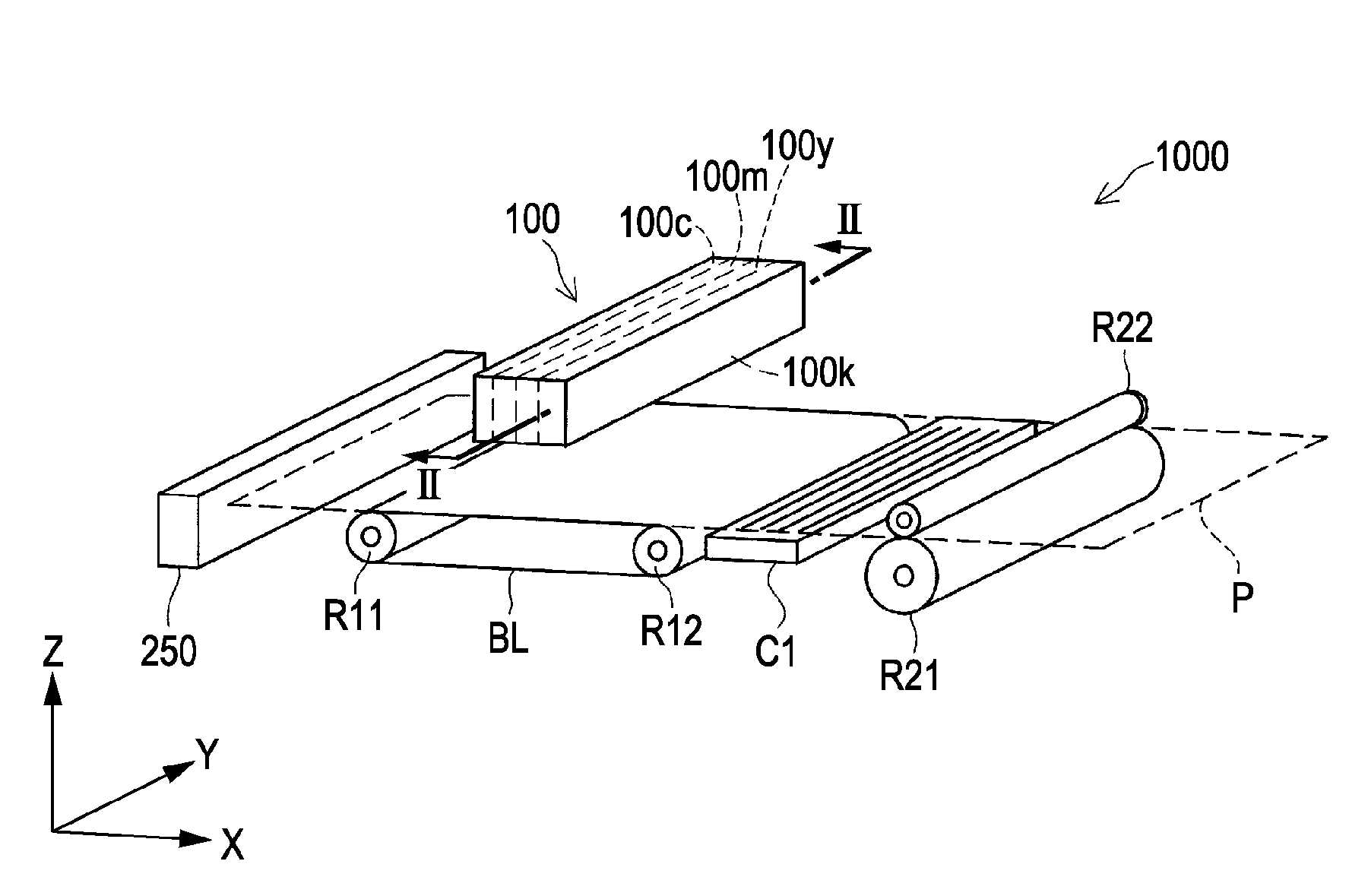
[0030]FIG. 1 is a perspective view that illustrates the schematic configuration of an ink jet printer, which serves as a fluid ejecting apparatus, according to an example embodiment of the invention. The printer 1000 includes a head 100, a cap C1, a paper feed device 250, a paper transport belt BL, two belt driving rollers R11 and R12 that drive the paper transport belt BL, and two paper delivery rollers R21 and R22. The cap C1 is arranged between the paper transport belt BL and the paper delivery roller R21.
[0031]At the time when printing is performed, the paper feed device 250 feeds a printing sheet of paper P in a positive X direction. The paper transport belt BL further transports the printing sheet of paper, which has been fed out from the paper feed device 250, in the positive X direction. The printing sheet of paper P, which has been transported by the paper transport belt BL, is delivered through between the two paper delivery rollers R21 and R22. ...
second example embodiment
B. Second Example Embodiment
[0052]FIG. 6 is a view that schematically illustrates circulation of ink between the head portion and the cap at the time of the preliminary discharge according to a second example embodiment. A printer (not shown) according to the second example embodiment differs from the printer 1000 (see FIG. 1 and FIG. 5) according to the first example embodiment in that a path through which ink returns from the ink discharge flow passage 220 to the ink tank 110k; however, the other configuration is the same.
[0053]Specifically, a head portion 100ka according to the second example embodiment does not include the pump P2 or the ink flow passage 140. On the other hand, the head portion 100ka includes an ink flow passage 170 that is in fluid communication with the ink tank 110k. The ink flow passage 170 reaches the outside of the head 100 through a valve B2. The valve B2 is an electromagnetic valve. The valve B2 is opened at the time of the preliminary discharge and is c...
third example embodiment
C. Third Example Embodiment
[0057]FIG. 7 is a view that schematically illustrates circulation of ink between the head portion and the cap C1 at the time of the preliminary discharge according to a third example embodiment. The head portion 100kb according to the third example embodiment differs from the head portion 100k (see FIG. 5) according to the first example embodiment in the following five points. That is, it differs in the cross-sectional area of the ink supply flow passage 120a that supplies ink to each of the nozzles nz, the amount of ink that flows through the two pumps P1 and P2, the configuration that the ink supply flow passage 120a is connected to the ink discharge flow passage 220, the path through which ink is supplied to the ink discharge flow passage 220, and the path through which ink is discharged from each of the ink supply flow passage 120a and the ink discharge flow passage 220. Note that the configuration of the head portions that correspond to the other thre...
PUM
 Abstract
Description
Claims
Application Information
 - R&D Engineer
- R&D Manager
- IP Professional
- Industry Leading Data Capabilities
- Powerful AI technology
- Patent DNA Extraction
Browse by: Latest US Patents, China's latest patents, Technical Efficacy Thesaurus, Application Domain, Technology Topic, Popular Technical Reports.
© 2024 PatSnap. All rights reserved.Legal|Privacy policy|Modern Slavery Act Transparency Statement|Sitemap|About US| Contact US: help@patsnap.com