Positive operating combine unloader discharge door arrangement

Active Publication Date: 2008-06-26
BLUE LEAF I P
View PDF9 Cites 11 Cited by
  • Summary
  • Abstract
  • Description
  • Claims
  • Application Information

AI Technical Summary

Benefits of technology

[0014]According to yet another a preferred aspect of the invention, the helical auger includes a helical flight extending around an auger shaft supported for rotation about a central longitudinal axis, the flight having an auger surface oriented at an acute angle to the auger shaft, and a bearing suppor

Problems solved by technology

However, when only a small amount of grain is present, which is inadequate to force the door open, this grain will only press against the closed door.
A problem that can arise with usage of a spring loaded dribble door is that this grain remaining in the unloading tube is susceptible to discharge and loss at inappropriate times. For instance, the grain can slosh out over the top of the door, or it can force the door open, such as when the unloading tube is in the more level stowed position even with the auger not operating.
This can occur, for instance as a result of a sudden acceleration of the combine or when traversing rough terrain, ditches and the like, and can leave a quantity or strip of grain on the ground.
Another problem that can occur when using a spring loaded dribble door is that, by design, the spring will oppose the opening of the door and the discharge

Method used


Image

  • Positive operating combine unloader discharge door arrangement
  • Positive operating combine unloader discharge door arrangement
  • Positive operating combine unloader discharge door arrangement

Examples


Example

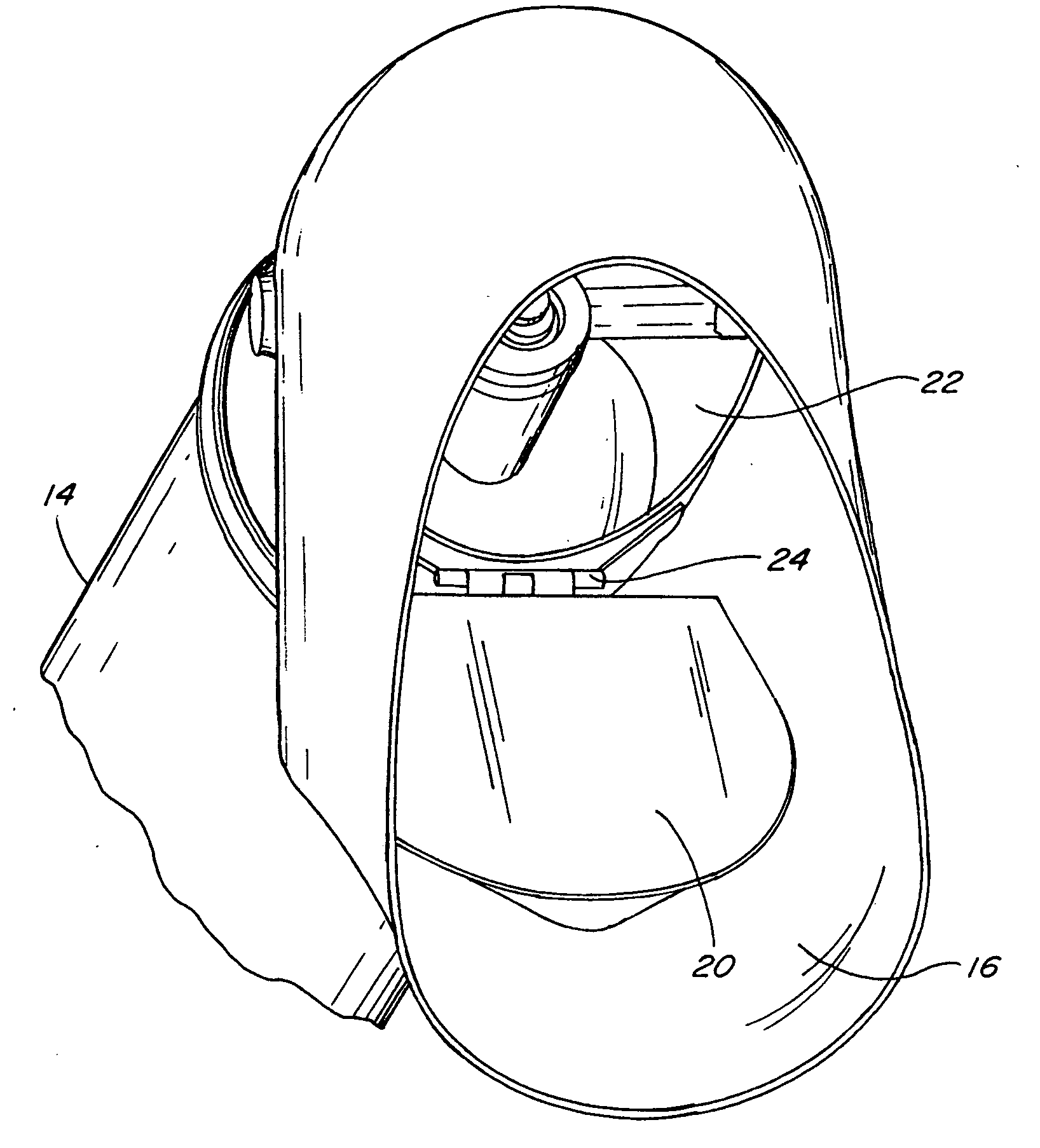
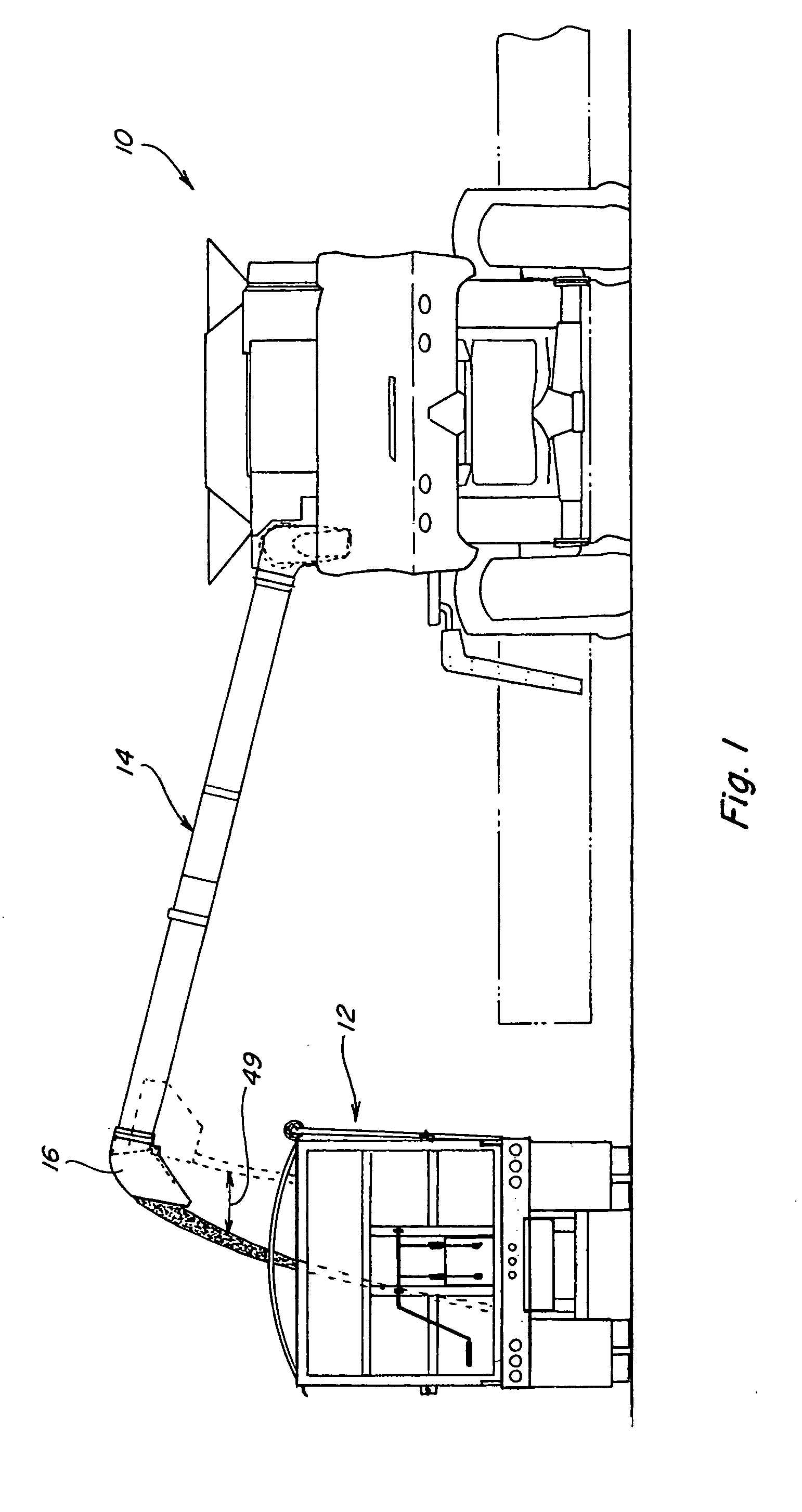
[0024]The invention will be described with reference to FIGS. 1, 2, 3A, 3B, 4, 5, 6A, and 6B wherein like numbers refer to like parts, FIG. 1 shows a rear view of a combine 10 unloading grain to a transport vehicle 12 through a cylindrical shaped unloading tube 14 and a spout 16. Grain is moved from combine 10 through unloading tube 14 by an auger 18 (see FIGS. 3A and 3B) in a well known manner.

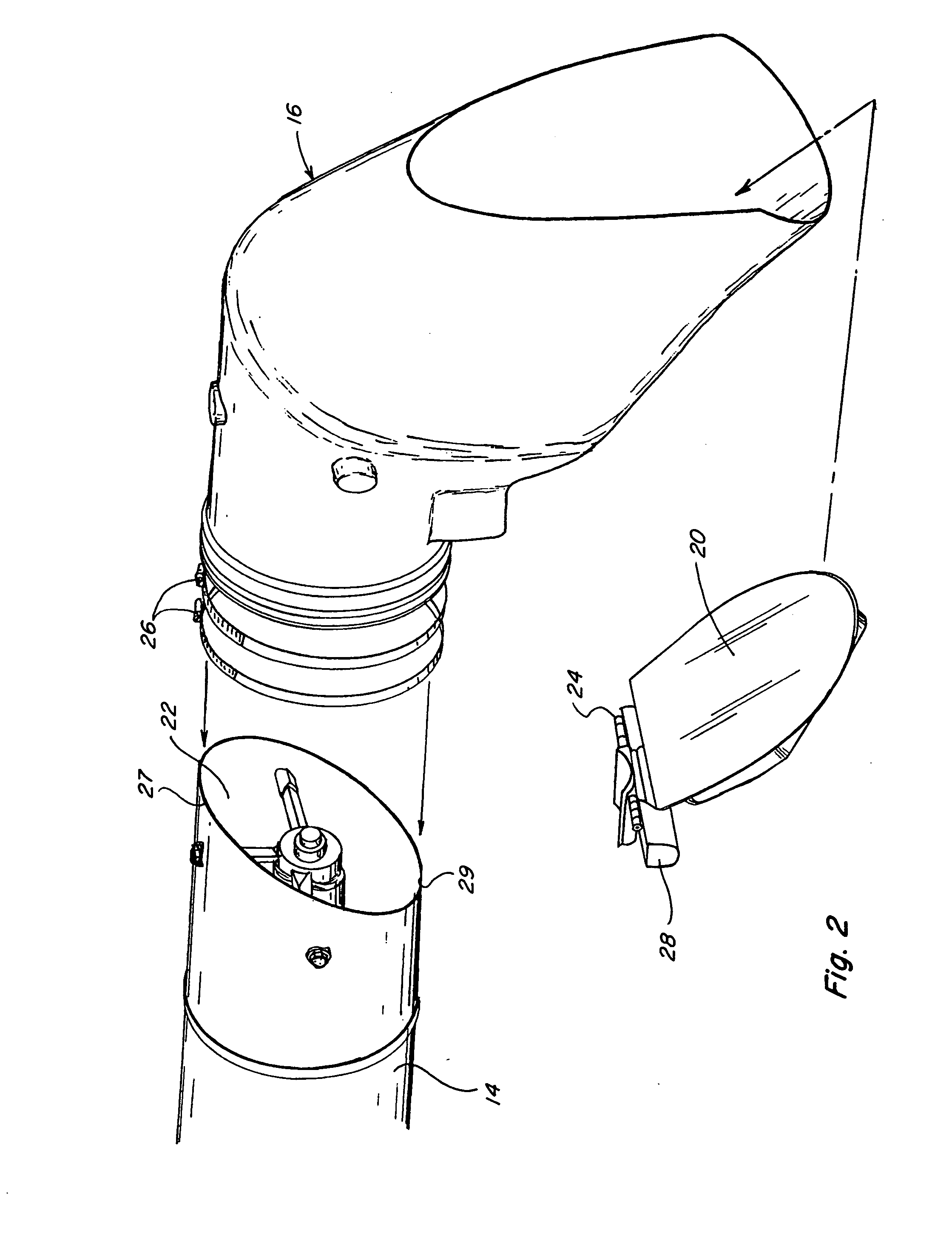
[0025]According to the invention, a discharge door 20 sized and shaped to cover discharge outlet 22, is pivotally attached adjacent discharge outlet 22, so as to be pivotally movable from a closed position covering discharge outlet 22 to an open position uncovering discharge outlet 22 as shown in FIGS. 2, 3A, 3B, and 4. Discharge spout 16 may connect to tube 14 adjacent to discharge outlet 22 accommodating door 20 and its attachment to tube 14 as shown in FIG. 2. Spout 16 may be held in place with one or more hose clamps 26 or the like. In a preferred embodiment of the invention, door 20 is m...


PUM


Abstract

A positive operating combine unloading discharge door which operates independent of the presence of grain in the unloading tube and is attached to the unloading tube to minimize opposition and obstruction to grain flow and completely cover the open end of the unloading tube when the unloading cycle is complete to minimize or eliminate grain loss due to grain dribble.

Description

TECHNICAL FIELD[0001]This invention relates generally to an agricultural harvesting machine unloading discharge system, and more particularly, to an unloading discharge door arrangement which is positively controlled for opening and closing independent of grain presence or unloading auger operation, and which can be configured to provide a cohesive discharge stream of grain which is less susceptible to wind drift and other problems.BACKGROUND ART[0002]The unloading tube on a combine harvester is comprised of a cylindrical housing, which encloses an auger. This tube is pivotally attached to the combine so as to allow it to swing out to a deployed operational position substantially normal to the direction of travel and extending upwardly for unloading, and swing into a more level, stowed position supported by its saddle, so as to extend rearwardly substantially parallel to the direction of travel the remainder of the time. The enclosed auger has helical flighting that when the auger i...

Claims


Application Information

Patent Timeline
IPC IPC(8): B65G47/00B65G33/00
CPCB65G33/08A01D41/1217
Inventor MCCULLY, WILLIAMCOOKSEY, WILLIAM L.WARDLOW, STEVEN M.JOHNSON, ORLIN W.
Owner BLUE LEAF I P
Why Eureka
Try Eureka