

Bond magnet and manufacturing method thereof, and actuator therewith
a manufacturing method and technology of bond magnets, applied in the direction of magnets, magnet powder mixtures, instruments, etc., can solve the problems of large fluctuation in microscopic density, difficult to further improve the performance of bond magnets, and limited improvement of the density of compression molded bodies consisting of the mixture of magnet powder and binder
- Summary
- Abstract
- Description
- Claims
- Application Information
AI Technical Summary
Benefits of technology
Problems solved by technology
Method used
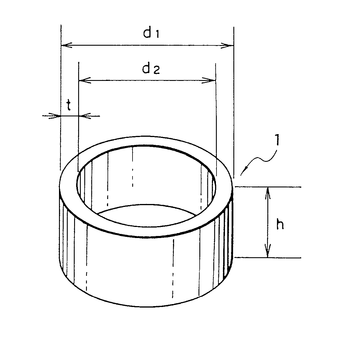
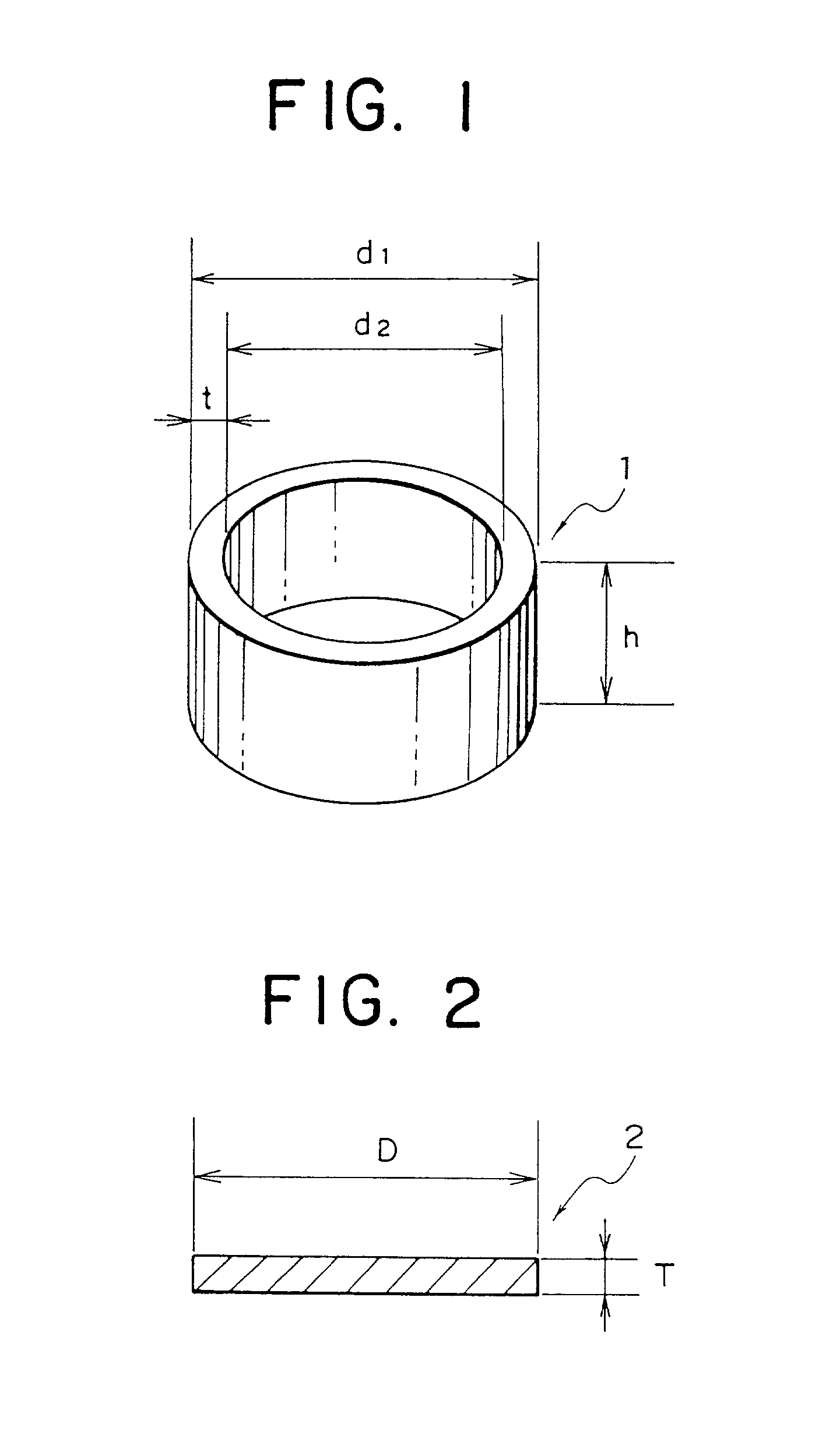
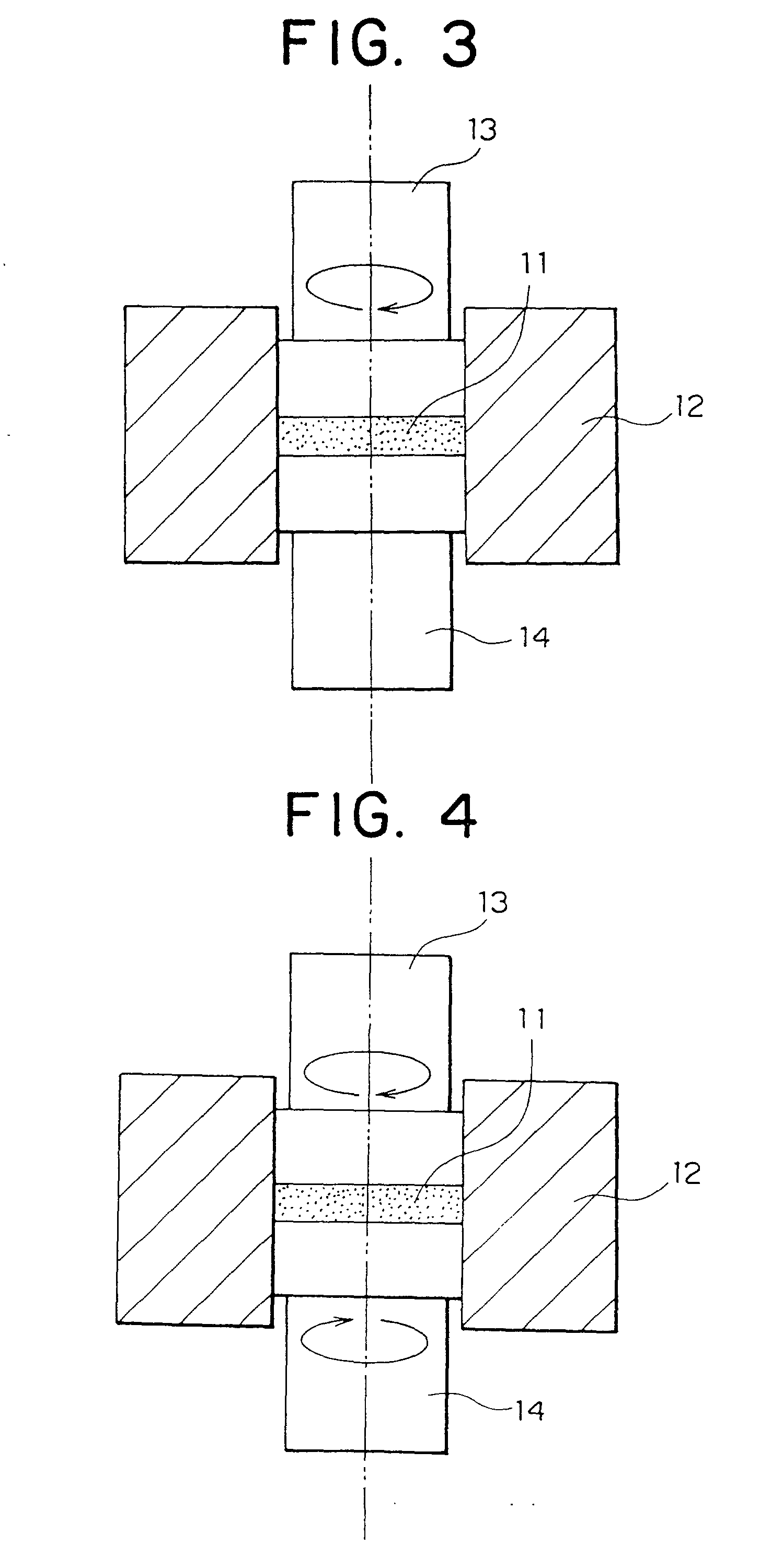
Image

Examples
embodiment 2
[0116] Embodiment 2
[0117] In the step of compression molding the aforementioned bond magnet of embodiment 1, with the exception of repetition times of the procedures (1) and (2) being set at the numbers shown in Table 2, identical with embodiment 1, the bond magnets are produced respectively. Each bond magnet is measured of the density. These results are shown together in Table 2.
2 TABLE 2 Number of Repetition of Combination of Density (1) and (2) (kg / m.sup.3) Comparative 1 5.94 .times. 10.sup.3 Example 2 Embodiment 2 2 6.02 .times. 10.sup.3 3 6.06 .times. 10.sup.3 5 6.12 .times. 10.sup.3 10 6.19 .times. 10.sup.3 15 6.22 .times. 10.sup.3
[0118] As shown in Table 2, as the number of repetition of the combined procedures of (1) and (2) is increased, the density of the bond magnet shows a tendency to increase. In particular, more than five times of repetitions can further improve the density of the bond magnet.
embodiments 3 to 10
[0119] Embodiments 3 to 10
Comparative Example 3 to 4
[0120] In the identical way with embodiment 1, an ingot of Sm--Zr--(Fe, Co)--B system master alloy is melted. Thereafter, the molten alloy is ejected from a nozzle onto a cooling roll rotating with a peripheral speed of 35 m / s to quench, thereby ribbons of alloy being produced. Thicknesses of the ribbons are 15 to 17 .mu.m. Further, as comparative examples 3 and 4, ribbons of alloy of a thickness of 300 .mu.m are produced with a roll peripheral speed of 1 m / s.
[0121] Subsequently, the aforementioned ribbons of alloy each is heat-treated in an atmosphere of Ar at 700.degree. C. for 30 minutes. The heat-treated ribbons of alloy, due to X-ray diffraction analysis, are confirmed for all diffraction peaks to be indexed to the TbCu.sub.7 crystal structure. Then, these ribbons of alloy are heat-treated in a flow of gas mixture (ratio of amounts of flow: NH.sub.3: H.sub.2=1:10) of NH.sub.3 and H.sub.2 under conditions of 420.degree. C..time...
embodiments 20 to 23
[0131] Embodiments 20 to 23
[0132] In the identical way with embodiment 1, an ingot of Sm--Zr--(Fe, Co)--B system master alloy is melted. Thereafter, the molten alloy is ejected from a nozzle onto a cooling roll rotating with a peripheral speed of 40 m / s to quench, thereby ribbons of alloy being produced. Thicknesses of the ribbon are 14 to 16 .mu.m.
[0133] Subsequently, the aforementioned ribbons of alloy each is heat-treated in an atmosphere of Ar at 700.degree. C. for 60 minutes. The heat-treated thin ribbons of alloy, due to X-ray diffraction analysis, are confirmed all diffraction peaks can be indexed to the TbCu.sub.7 crystal structure. Then, these ribbons of alloy are heat-treated in an atmosphere in which a ratio of flow rates of NH.sub.3 and H.sub.2 is 1:20 under conditions of 440.degree. C..times.4 hours to introduce nitrogen, thereafter being heat-treated at the same temperature for two hours in an atmosphere of nitrogen to form magnet materials.
[0134] The aforementioned ma...
PUM
| Property | Measurement | Unit |
|---|---|---|
| Percent by mass | aaaaa | aaaaa |
| Thickness | aaaaa | aaaaa |
| Diameter | aaaaa | aaaaa |
Abstract
Description
Claims
Application Information