Sw-sagd with between heel and toe injection

Inactive Publication Date: 2016-10-27
CONOCOPHILLIPS CO
View PDF8 Cites 12 Cited by
  • Summary
  • Abstract
  • Description
  • Claims
  • Application Information

AI Technical Summary

Benefits of technology

[0023]The conventional SW-SAGD utilizing one single horizontal well to inject steam into reservoir through toe and produce liquid (oil and water) through mid and heel of the well has potential for thin-zone applications where

Problems solved by technology

The conventional SW-SAGD utilizing one single horizontal well to inject steam into reservoir through toe and produce liquid (oil and water) through mid and heel of the well has potential for thin-zone applications where placing two horizontal wells with 5 m vertically apart required in the SAGD is technically and economically challenging.
SW-SAGD,

Method used


Image

  • Sw-sagd with between heel and toe injection
  • Sw-sagd with between heel and toe injection
  • Sw-sagd with between heel and toe injection

Examples


Embodiment Construction

[0085]The present disclosure provides a novel well configurations and method for SW-SAGD.

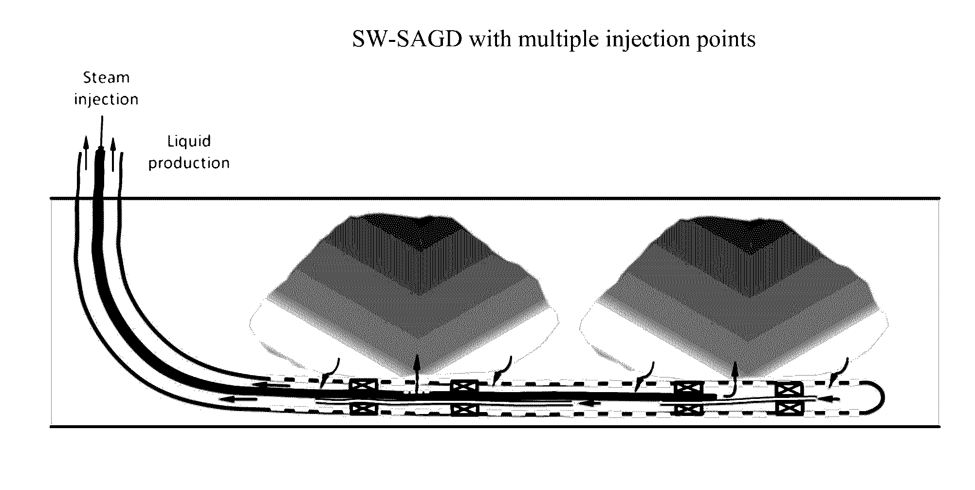
[0086]This novel modification to the conventional single-well SAGD (SW-SAGD) process varies the location and number of steam injection points during the production phase, and the same points can be used in preheat or cyclic preheat.

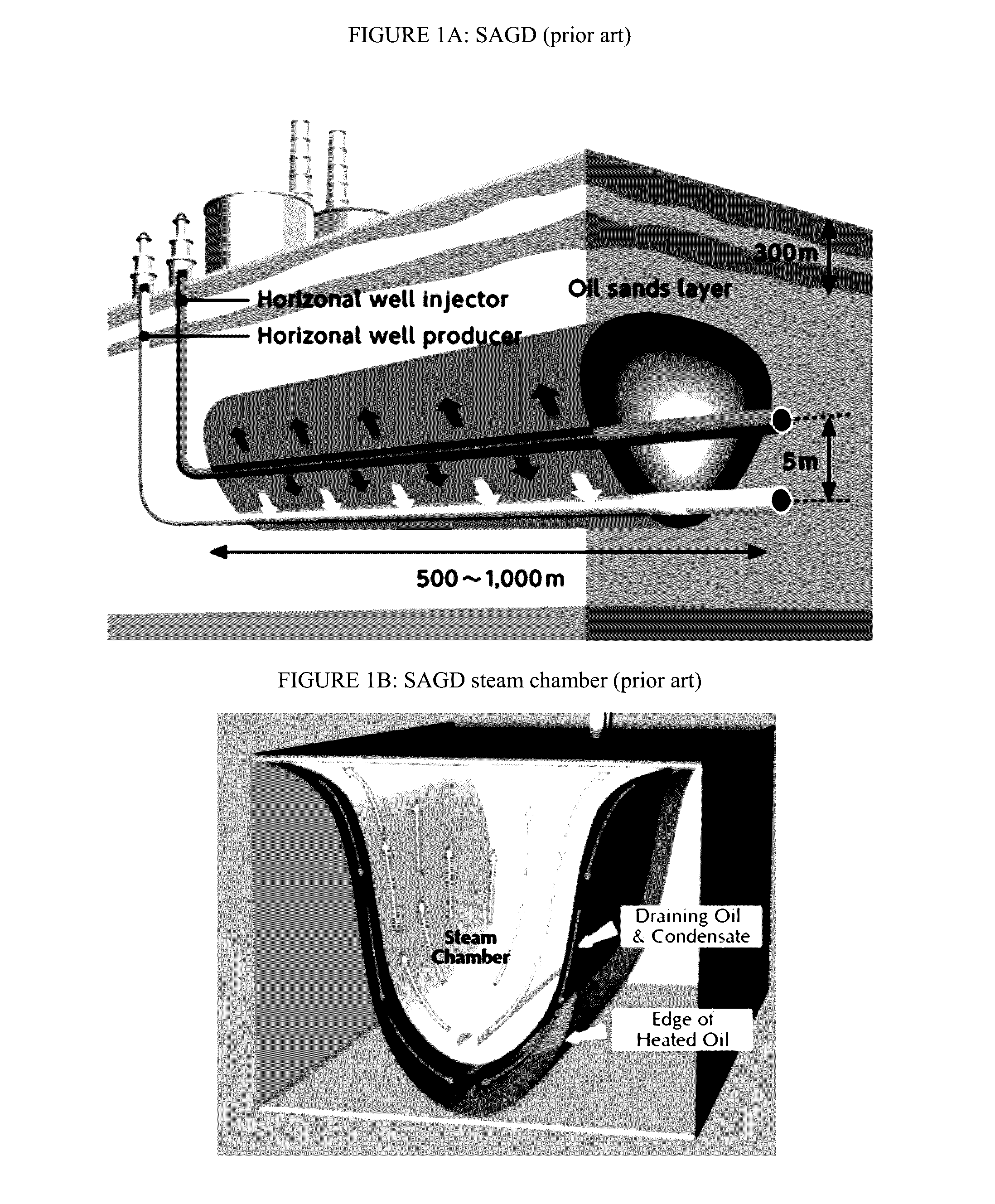
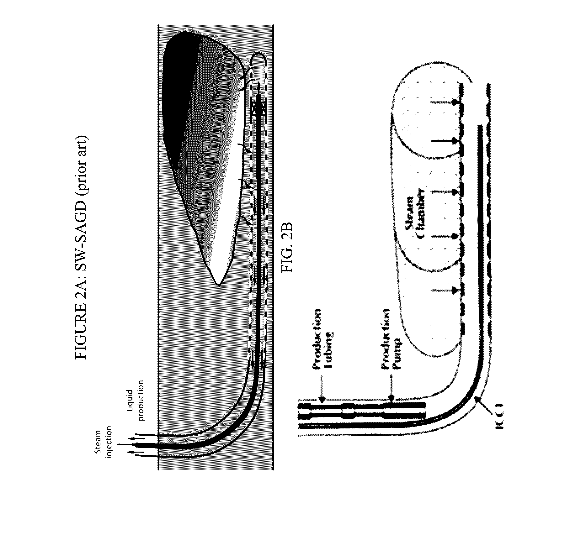
[0087]The conventional SW-SAGD process grows a steam chamber and drains oil by gravity by utilizing one single horizontal well with steam injected only at the toe and liquid produced through the rest of the well. SW-SAGD has potential to unlock vast thin-zone (5-20 m pay) oil sand resources where SAGD using well pairs is economically and technically challenging.

[0088]However, the conventional SW-SAGD normally suffers from slow steam chamber growth and low oil production rate as the steam chamber can only grow from toe gradually towards the heel. This appears to be very ineffective, and seriously limits the usefulness of SW-SAGD.

[0089]In this invention, we propose an i...


PUM


Abstract

The present disclosure relates to a particularly effective well configuration that can be used for single well steam assisted gravity drainage (SW-SAGD), wherein steam injection occurs at one or more points between the heel and toe, instead of at the toe as in the prior art.

Description

PRIORITY CLAIM[0001]This application is a non-provisional application which claims benefit under 35 USC §119(e) to U.S. Provisional Application Ser. No. 62 / 153,269 filed Apr. 27, 2015, entitled “SW-SAGD WITH BETWEEN HEEL AND TOE INJECTION,” which is incorporated herein in its entirety.FEDERALLY SPONSORED RESEARCH STATEMENT[0002]Not Applicable.REFERENCE TO MICROFICHE APPENDIX[0003]Not applicable.FIELD OF THE DISCLOSURE[0004]This disclosure relates generally to methods that can advantageously produce oil using steam-based mobilizing techniques. In particular, it relates to improved single well gravity drainage techniques with better steam chamber development than previously available.BACKGROUND OF THE DISCLOSURE[0005]Oil sands are a type of unconventional petroleum deposit, containing naturally occurring mixtures of sand, clay, water, and a dense and extremely viscous form of petroleum technically referred to as “bitumen,” but which may also be called heavy oil or tar. Bitumen is so h...

Claims


Application Information

Patent Timeline
IPC IPC(8): E21B43/24E21B33/12E21B17/20E21B43/30
CPCE21B43/2406E21B17/203E21B33/12E21B43/305E21B43/162
Inventor CHEN, QINGMENARD, WENDELL P.
Owner CONOCOPHILLIPS CO
Why Eureka
Try Eureka