Optical imaging system for unmanned aerial vehicle

an optical imaging and unmanned aerial vehicle technology, applied in the field of optical imaging, can solve the problems of reducing the amount of flight time required to observe a given area, narrow mission field of view, and inability to zoom in and ou

Active Publication Date: 2009-01-15
SOUTHWEST RES INST
View PDF8 Cites 135 Cited by
  • Summary
  • Abstract
  • Description
  • Claims
  • Application Information

AI Technical Summary

Problems solved by technology

These cameras have a larger field of view (FOV) than fixed mount cameras, and thus decrease the amount of flight time required to observe a given area.
For small UAV's, the cameras are typically implemented with fixed mount systems,...

Method used


Image

  • Optical imaging system for unmanned aerial vehicle
  • Optical imaging system for unmanned aerial vehicle
  • Optical imaging system for unmanned aerial vehicle

Examples


Embodiment Construction

[0023]As explained below, the system and method described herein use one or more fixed image sensors to implement an on-board UAV camera. Images are acquired, processed, and delivered to a ground station in accordance with military (NTSC) formats. The images are processed and manipulated in a manner that provides the user with a wide selection of view modes. The design of the system addresses various issues that arise for UAV-mounted camera systems, such as of weight, size, low power usage, as well as communications with a ground station.

System Overview

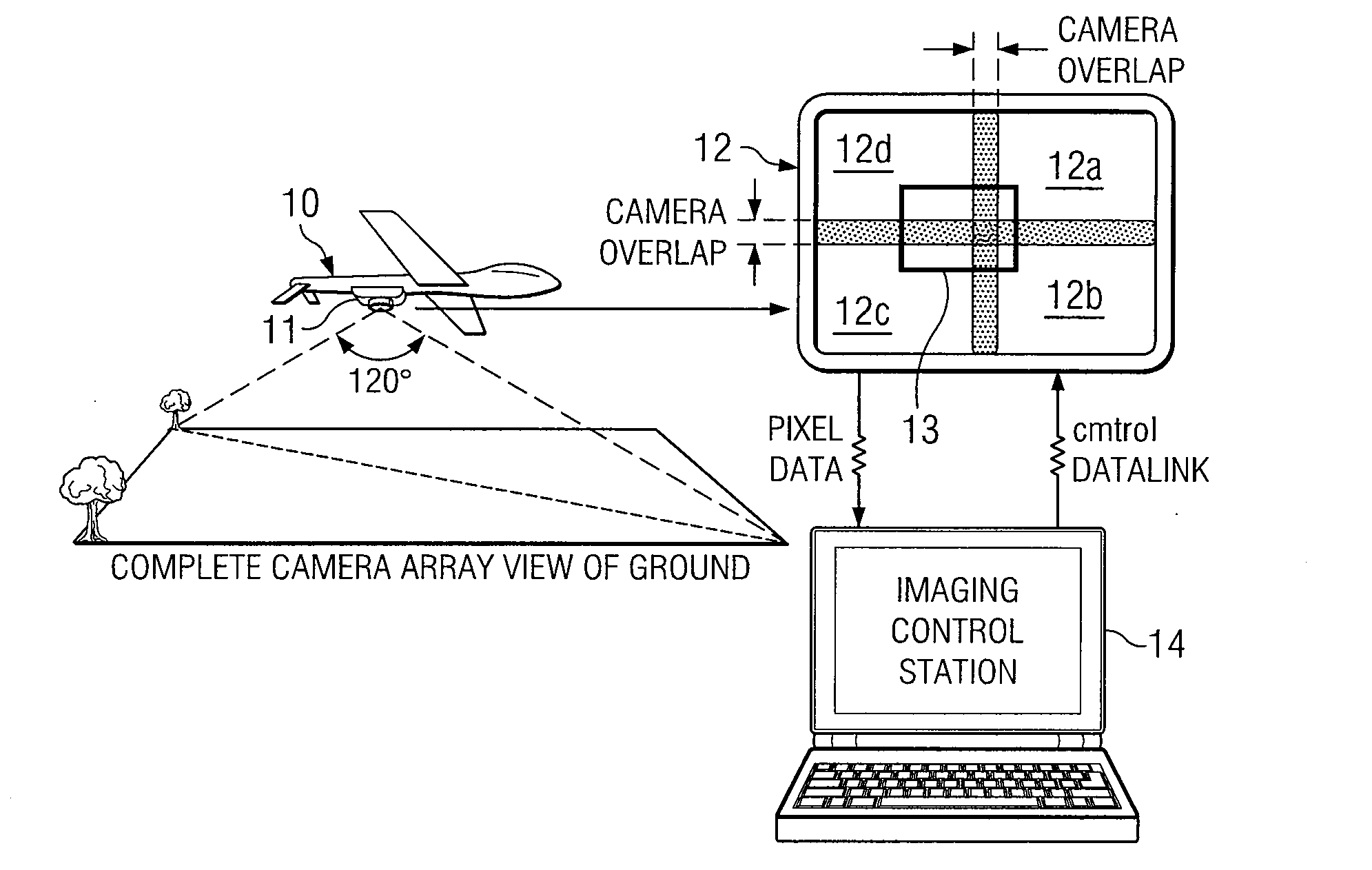
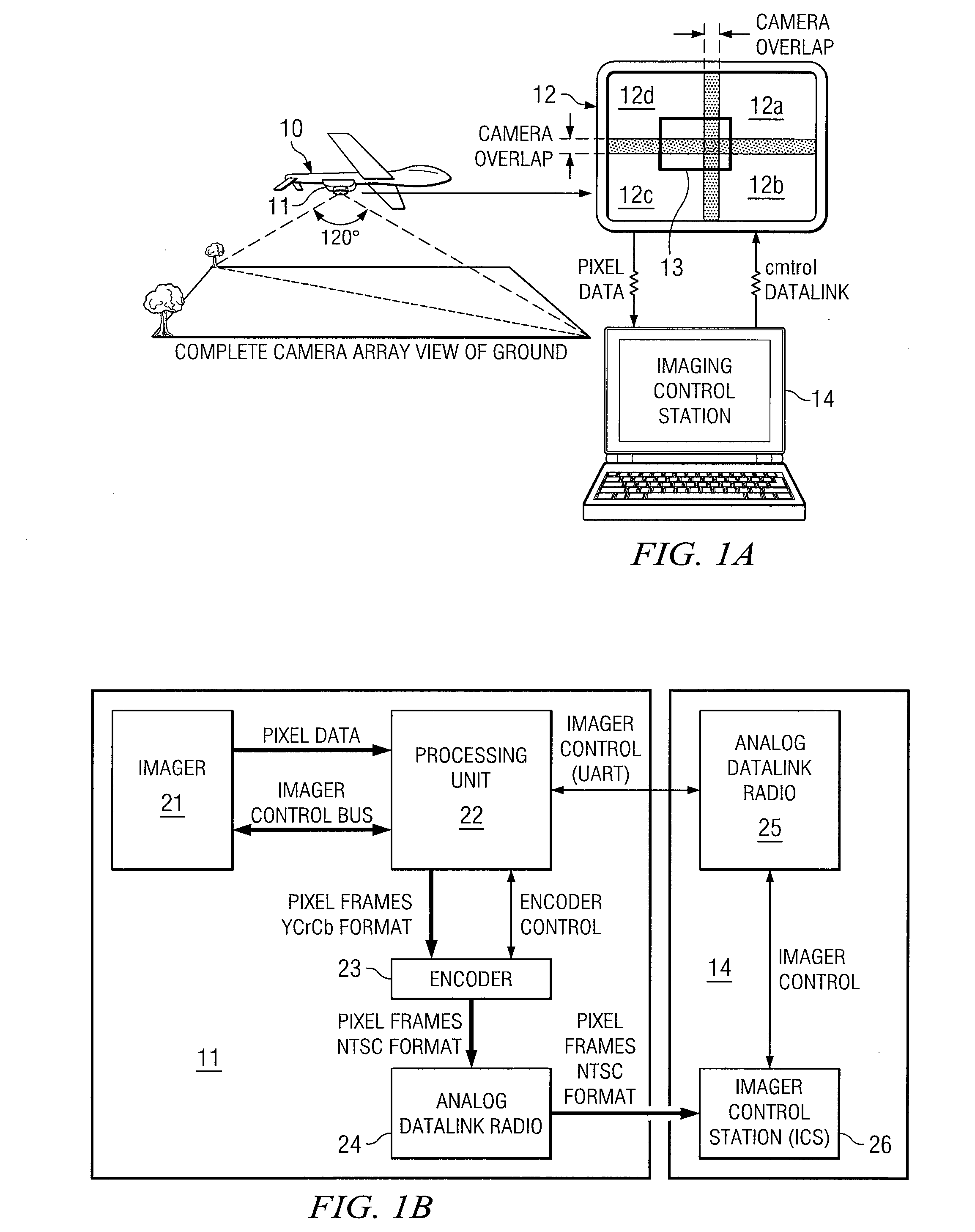
[0024]FIG. 1A illustrates a UAV10 having an on-board camera unit 11 in communication with a remote ground-based image control station 14 in accordance with the invention. Camera unit 11 produces images 12, and a selected ROI 13 from image 12 is transmitted to the image control station 14.

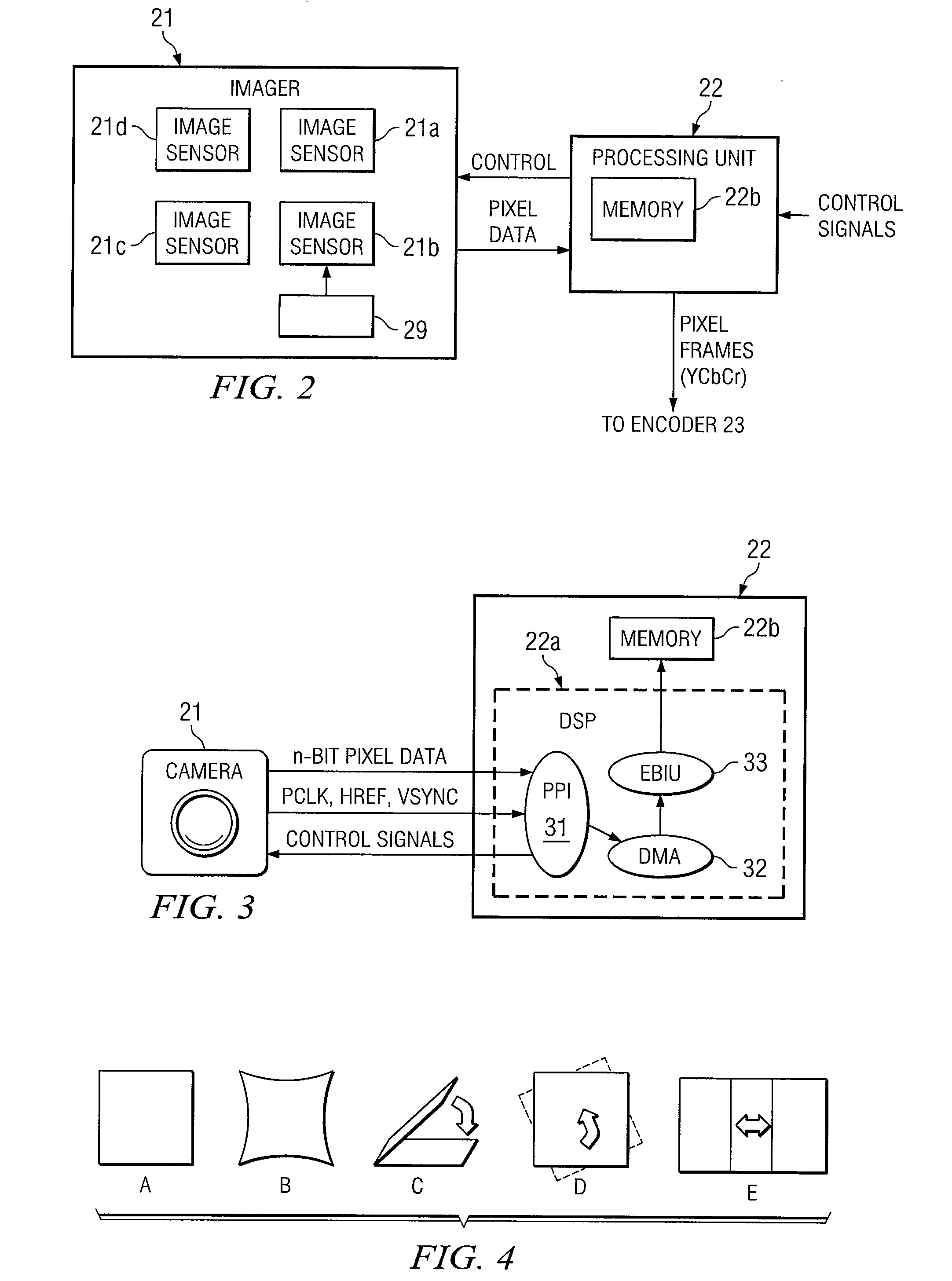
[0025]FIG. 1B illustrates camera unit 11, image control station 14, and the datalinks between them, in further detail. The imager 21 of camera unit 1...


PUM


Abstract

An optical imaging system and associated methods for capturing images from an aircraft, such as a UAV. A camera unit on-board the aircraft is remotely controlled from an image control station. The image control station receives image data from the camera unit, and also delivers control signals for determining a viewing mode of the image.

Description

RELATED PATENT APPLICATION[0001]This application claims the benefit of U.S. Provisional Application No. 60 / 745,932, filed Apr. 28, 2006 and entitled “Optical Imaging System for Unmanned Aerial Vehicle.”TECHNICAL FIELD OF THE INVENTION[0002]This invention relates to optical imaging, and more particularly to an optical imaging system especially designed for use in a small unmanned aerial vehicle (UAV).BACKGROUND OF THE INVENTION[0003]For troop protection, military surveillance missions often use autonomous vehicles, such as unmanned aerial vehicles (UAV's). The UAV flys a short low altitude flight, and uses an on-board camera system to acquire images, which it then delivers to a ground station.[0004]A typical UAV camera system is a color system that is implemented with commercial off-the-shelf products. Some UAV's have a gimbaled pan / zoom / tilt (PZT) camera to acquire images. These cameras have a larger field of view (FOV) than fixed mount cameras, and thus decrease the amount of fligh...

Claims


Application Information

Patent Timeline
IPC IPC(8): H04N7/18
CPCH04N7/185G01C11/025
Inventor ALLEY, KEVINLOPEZ, ROGERSOMERS, RICHARD
Owner SOUTHWEST RES INST
Why Eureka
Try Eureka