Ring lamp for illuminating a delimited volume and the use thereof

Inactive Publication Date: 2009-01-15
STIFTUNG ALFRED WEGENER INSTITUT FUER POLAR UND MEERESFORSCHUNG
View PDF12 Cites 1 Cited by
  • Summary
  • Abstract
  • Description
  • Claims
  • Application Information

AI Technical Summary

Benefits of technology

[0006]Starting from the ring lamp of the closest publication, the objective of the present invention is to put forward a ring lamp of the generic type explained above, which is capable of providing a particularly bright illumination of a volume that is strictly delimited in all three spatial dimensions. In this context, the ring lamp should be simple, it should be sturdy in terms of its structure and its handling, and it should be inexpensive to produce. As the inventive solution to achieve this objective, the present invention is characterized in that the device to direct the light emission is formed by a lens system having

Problems solved by technology

The thinner the disk of light is, the less light is scattered towards the outside by the plankters passing through and reflected from the plankters that are still or once again un-illu

Method used


Image

  • Ring lamp for illuminating a delimited volume and the use thereof
  • Ring lamp for illuminating a delimited volume and the use thereof
  • Ring lamp for illuminating a delimited volume and the use thereof

Examples


Example

[0016]Embodiments of the ring lamp according to the invention will be explained in greater detail below making reference to the schematic figures. The following is shown:

[0017]FIG. 1—a top view of a ring lamp without the top cover;

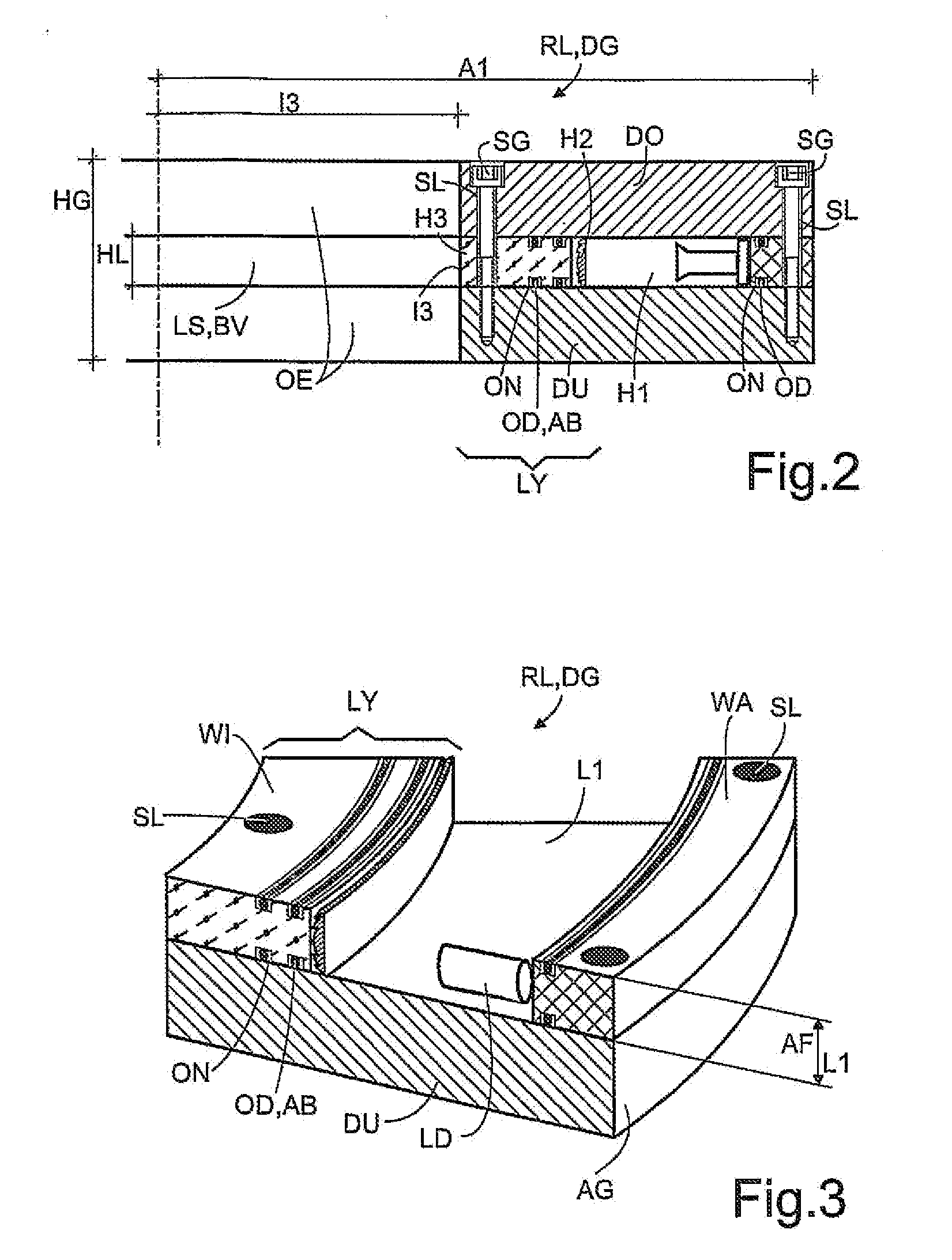
[0018]FIG. 2—a sectional view along the X-X marking in FIG. 1;

[0019]FIG. 3—a perspective view of a section of the ring lamp according to FIG. 1;

[0020]FIG. 4—the optical path of the ring lamp according to FIG. 1; and

[0021]FIG. 5—an embodiment of the ring lamp with a 45° deflection mirror.

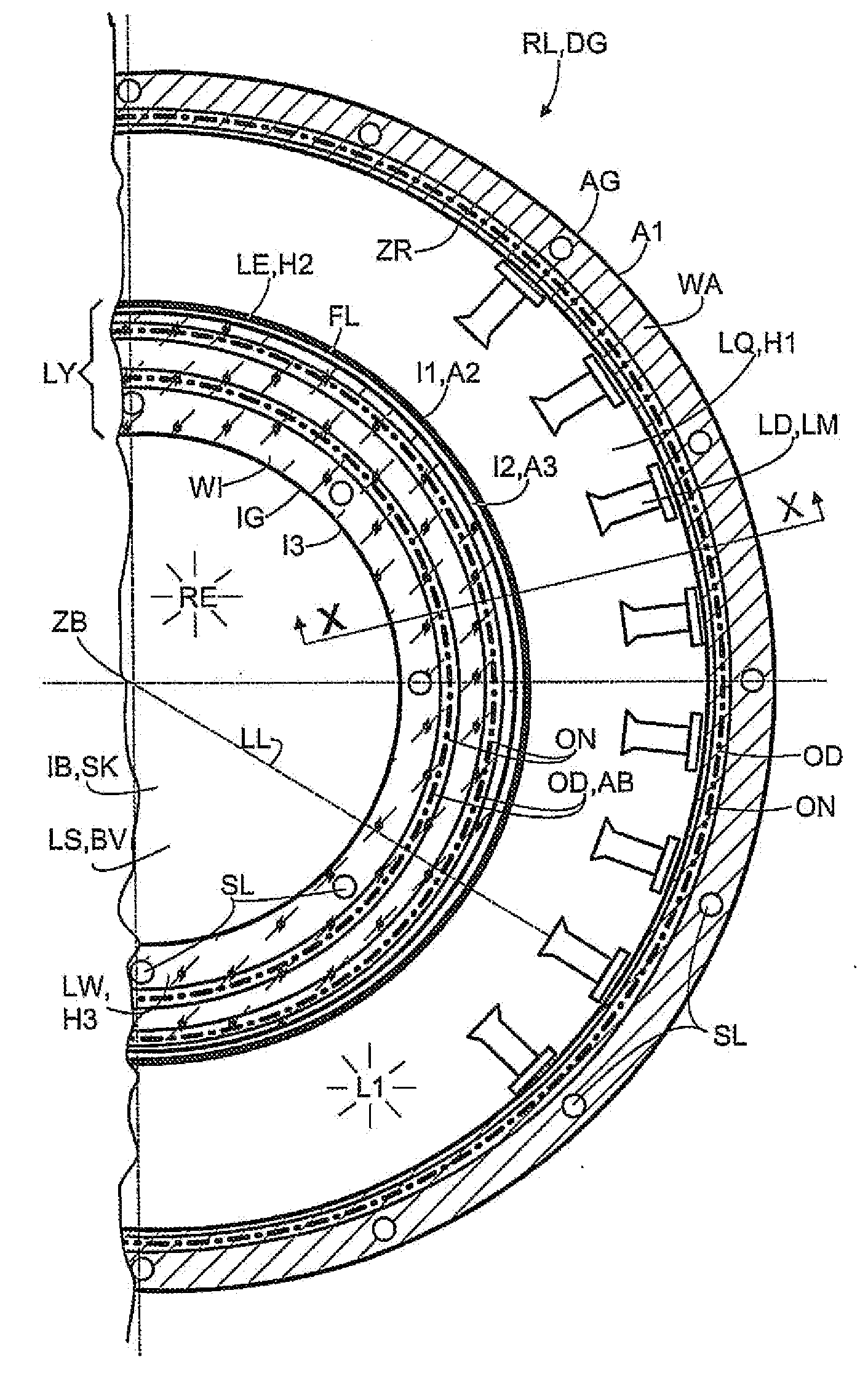
[0022]FIG. 1 shows a top view of a ring lamp RL without the top cover DO, which can possibly be used in a video plankton recorder. The light source LQ, which is configured as a hollow cylinder H1, is arranged all the way on the outside. The outer contour A1 of the light source at the same time demarcates the outer edging AG of the pressure-proof housing DG that encloses the ring lamp RL. Its inner contour I1 is at the same time the outer contour A2 of the other hollow cylin...


PUM


Abstract

A ring lamp includes a light source having a first hollow cylinder with a lighting device disposed therein. The light source has an emitting surface with a light-emitting direction oriented toward an axis of the hollow cylinder. The lamp also includes a light directing device configured to direct light emission. The light directing device includes a lens system having a lens formed as a second hollow cylinder and configured to focus light into a radial plane which is orthogonal to the axis. The lens system has a ring-shaped aperture diaphragm disposed centrally in an optical path of the light emission behind the lens. The emitting surface of the light source and the lens system have a same length, are coaxial and axially aligned with each other. A radial surface which is defined by an inner radius of the lens system and the length of the lens system spans a delimited volume.

Description

[0001]The invention relates to a ring lamp having a light source configured as a hollow cylinder with an illuminating means and having a device to direct the light emission, whereby the light source has an emitting surface with a light-emitting direction oriented towards the axis of the hollow cylinder.[0002]Such ring lamps are employed, for example, in camera objectives used for macrophotography, as operating theater illumination in medicine or else for transmitted-light or reflected-light illumination in optical microscopy. In this context, such a ring lamp is arranged concentrically to the optical axis of the image-forming optical system. Therefore, in contrast to spot illumination, the object to be imaged is illuminated without any shadows. Shadowless, uniform and intense illumination is also needed in the field of particle detection in currents, but only within a delimited volume, as a result of which only the particles that enter the illuminated area with the current are obser...

Claims


Application Information

Patent Timeline
IPC IPC(8): F21S8/00
CPCF21S8/00G01N15/1459G01N21/51G01N21/53G01N2201/0638G01N2021/4759G01N2021/4769G01N2201/0218G01N2201/062G01N2015/1493
Inventor SCHULZ, JAN
Owner STIFTUNG ALFRED WEGENER INSTITUT FUER POLAR UND MEERESFORSCHUNG
Why Eureka
Try Eureka