
Circuit and method for correlated inputs to a population count circuit

a population count and input circuit technology, applied in the field of semiconductor circuits, can solve the problems of large circuit area required to implement population counts of large data values, inefficient computation, and large circuit area

Inactive Publication Date: 2009-01-15
NXP USA INC
View PDF5 Cites 5 Cited by
  • Summary
  • Abstract
  • Description
  • Claims
  • Application Information

AI Technical Summary

Benefits of technology

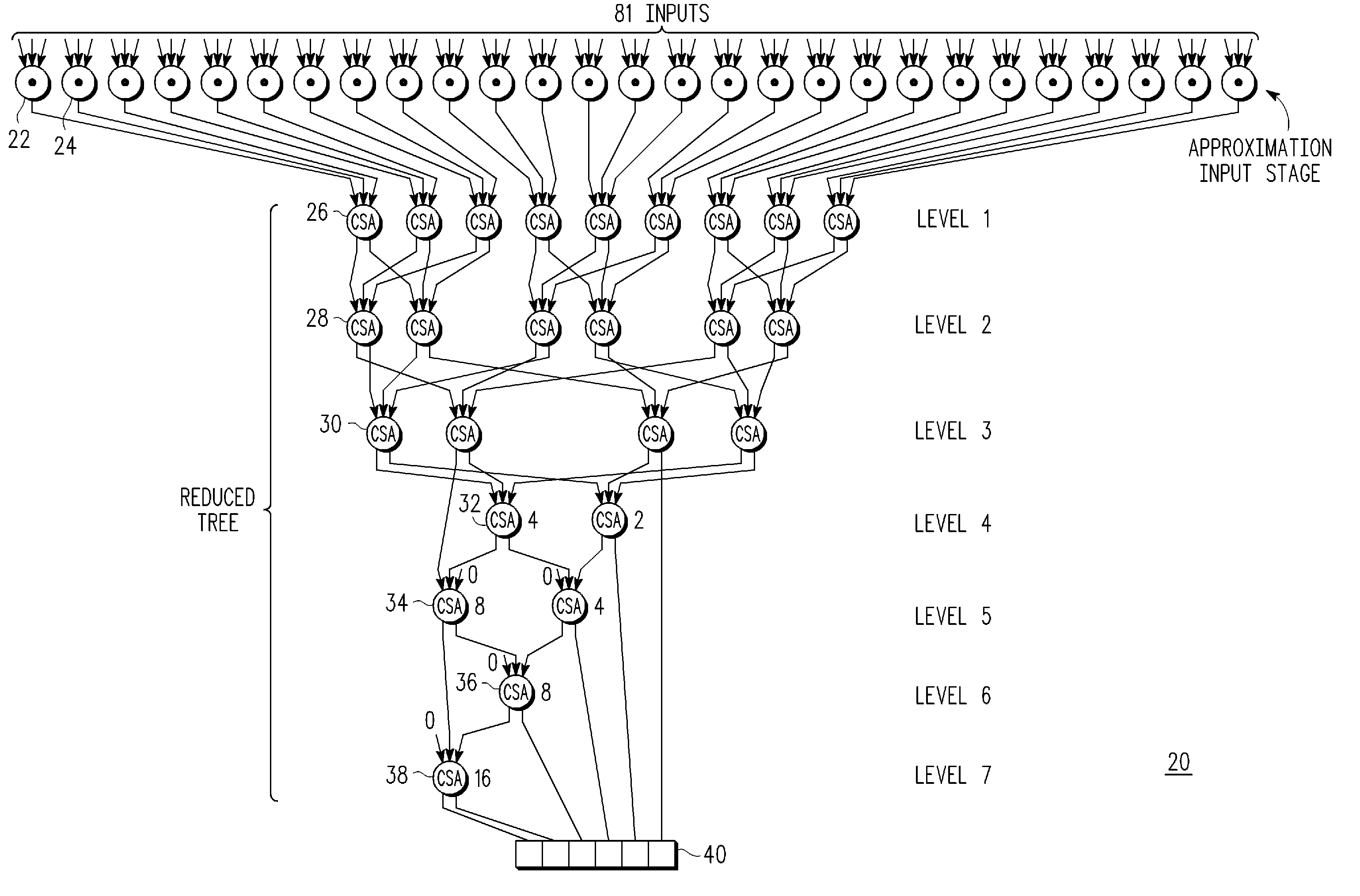
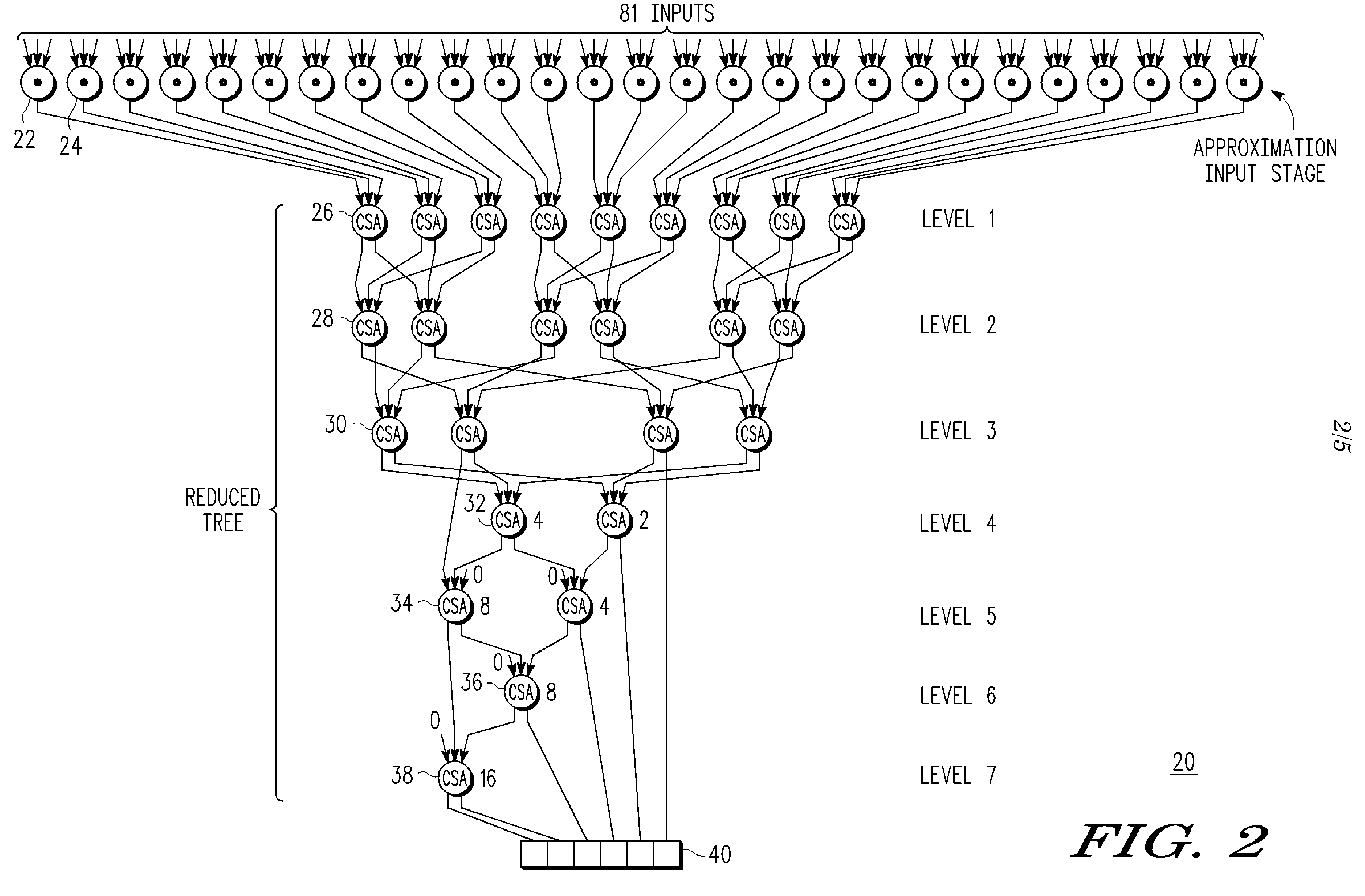
The present invention relates to a semiconductor circuit that implements a population count circuit for counting logic "1" bits in data. The circuit is designed to address issues with the known circuit, such as large circuit area and slow operation. The invention proposes a population count approximation circuit that uses a tree structure with fewer circuit elements and logic gates, resulting in a smaller and faster circuit. The circuit uses a plurality of predetermined logic gates to approximate the count of bit values at predetermined points in the integrated circuit. The technical effect of the invention is to provide a more efficient and faster way to count logic "1" bits in data.

Problems solved by technology

For data vectors containing a large number of bits, such as sixty-four or one hundred twenty-eight bits, the circuitry and the total delay required to perform the counting of the logic “1” bits is typically very large and inefficient.
Significant time delays for a popcount operation are unacceptable in many applications such as high speed communication systems.
In addition to the delay associated with known population count circuits, a large amount of circuit area is required to implement population counts of large data values.
The extra circuit area results in additional costs where additional area can be afforded.
In portable wireless applications, the additional area is prohibitive and thus the population count function cannot be implemented.
In either situation, where a large number of sample points is required to be checked, the accumulation of a total count of bits of predetermined logic value is costly and time inefficient.

Method used


Image

  • Circuit and method for correlated inputs to a population count circuit
  • Circuit and method for correlated inputs to a population count circuit
  • Circuit and method for correlated inputs to a population count circuit

Examples


Embodiment Construction

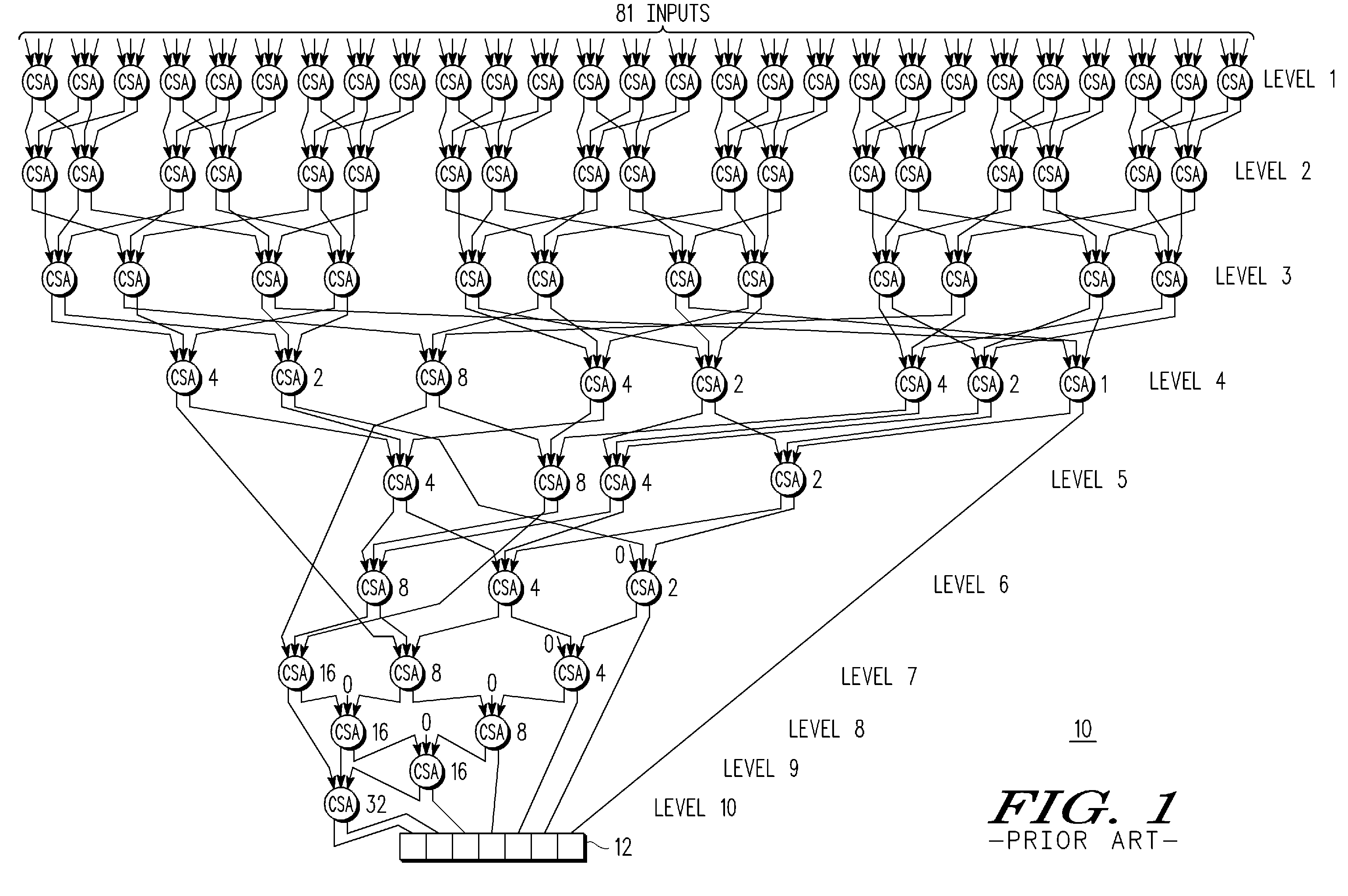
[0012]Illustrated in FIG. 1 is a known population count circuit 10. In the illustrated form a total of 81 input bits are shown. This number is arbitrarily chosen for illustration purposes only. The population count circuit 10 stores a data value in a register 12 that indicates how many logic “1” bit values exist among the 81 input bits. Within the population count circuit 10 are ten levels of three-input carry-save-adder (“CSA”) circuits. Each carry-save-adder circuit provides two outputs. A right-hand output has a binary weighting of 20 and a left-hand output has a binary weighting of 21. Between the first level and second level of carry-save-adder circuits, the number of inputs has been reduced by a factor of three-to-two. A similar reduction in number of inputs occurs in each of the remaining levels 3, 4, 5, 6, 7, 8, 9 and 10. In some situations within levels 6, 7, 8 and 9 there are extra inputs for the carry-save-adder circuits. These inputs are permanently connected to a logic ...


PUM


Abstract

A circuit includes a plurality of selection circuits. Each of the plurality of selection circuits has a first input, a second input, a control input, and an output. Each of the first inputs receives one of a plurality of correlated signals. Each of the second inputs receives one of a plurality of uncorrelated signals. Each of the control inputs receives a correlation mode control signal, and each of the outputs provides the one of the plurality of correlated signals or the one of the plurality of uncorrelated signals based on the correlation mode control signal. The circuit further includes a population count circuit having a plurality of data inputs coupled to receive the outputs of the plurality of selection circuits. The population count circuit provides a population count for the plurality of data inputs. The population count may be an approximate count or an accurate count.

Description

RELATED APPLICATION[0001]This application is related to our copending U.S. patent application Ser. No. (Attorney Docket No. NC45245TH) entitled “Population Count Approximation Circuit and Method Thereof” filed of even date herewith and assigned to the same assignee hereof.BACKGROUND[0002]1. Field[0003]This disclosure relates generally to semiconductors, and more specifically, to semiconductor circuits that implement counting circuitry.[0004]2. Related Art[0005]Population count (“popcount”) circuits function to output the number of logic “1” bits in data such as an input word or a vector value. For example, a population count is performed on a vector to determine the amount of nonzero elements within the vector. This function is useful for a variety of purposes including the testing or checking for failures in the expected operation of an integrated circuit, such as a communications processor or a memory. For data vectors containing a large number of bits, such as sixty-four or one h...

Claims


Application Information

Patent Timeline
Patent Type & Authority Applications(United States)
IPC IPC(8): G06M3/00
CPCG06F7/607
Inventor MOYER, WILLIAM C.TAYLOR, KELLY K.
Owner NXP USA INC
Learn More