
Optical wavelength multiplexing access system

a wavelength multiplexing and access system technology, applied in the field of optical wavelength multiplexing access system, to achieve the effect of critical economics and advantageous network expansion

Active Publication Date: 2009-01-15
NIPPON TELEGRAPH & TELEPHONE CORP
View PDF16 Cites 52 Cited by
  • Summary
  • Abstract
  • Description
  • Claims
  • Application Information

AI Technical Summary

Benefits of technology

The present invention provides an optical TX / RX device for transmitting and receiving wavelength-multiplexed signal light in a star-type network without using monitoring light. The device includes an optical RX means capable of varying RX wavelength, an optical TX means capable of varying TX wavelength, a detection means for detecting RX wavelengths not in use, and a wavelength control means for assigning the RX wavelength to one of the RX wavelengths detected by the detection means and for assigning the TX wavelength to a TX wavelength corresponding to the assigned RX wavelength. The detection means scans the RX wavelengths and detects the RX wavelengths not in use by measuring the RX power on each of the RX wavelengths. The network includes a plurality of optical TX / RX devices connected via a power splitter. The method of assigning wavelengths includes detecting downstream wavelengths not in use, selecting one of the detected wavelengths, transmitting a signal light at the selected wavelength, detecting a response to the transmitted signal light, and initiating communication with the optical line terminal using the selected wavelength if the response is detected. The optical TX / RX device can be applied to various transmission frame formats and is especially advantageous for network expansion with small start-ups.

Problems solved by technology

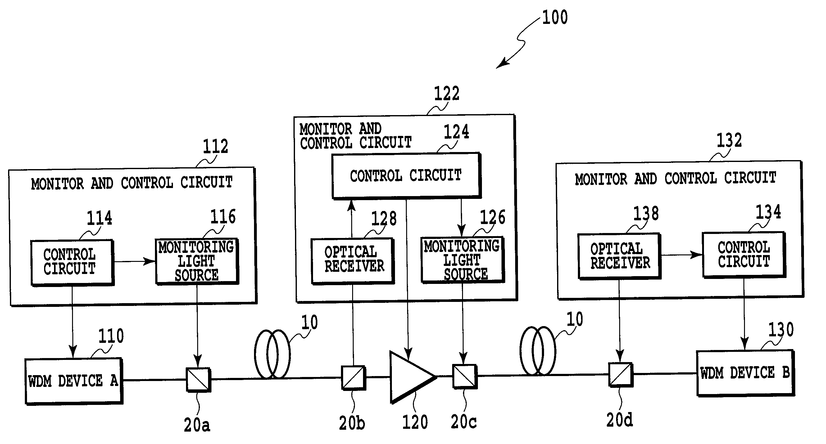
However, since the monitoring light is used in such a configuration, optical components such as light sources 116, 126, multiplexers 20a, 20c, demultiplexers 20b, 20d, and optical receivers 128, 138 are required, which are costly.

Method used


Image

  • Optical wavelength multiplexing access system
  • Optical wavelength multiplexing access system
  • Optical wavelength multiplexing access system

Examples


Embodiment Construction

[0035]Hereinafter, embodiments of the present invention will be described in detail with reference to the drawings.

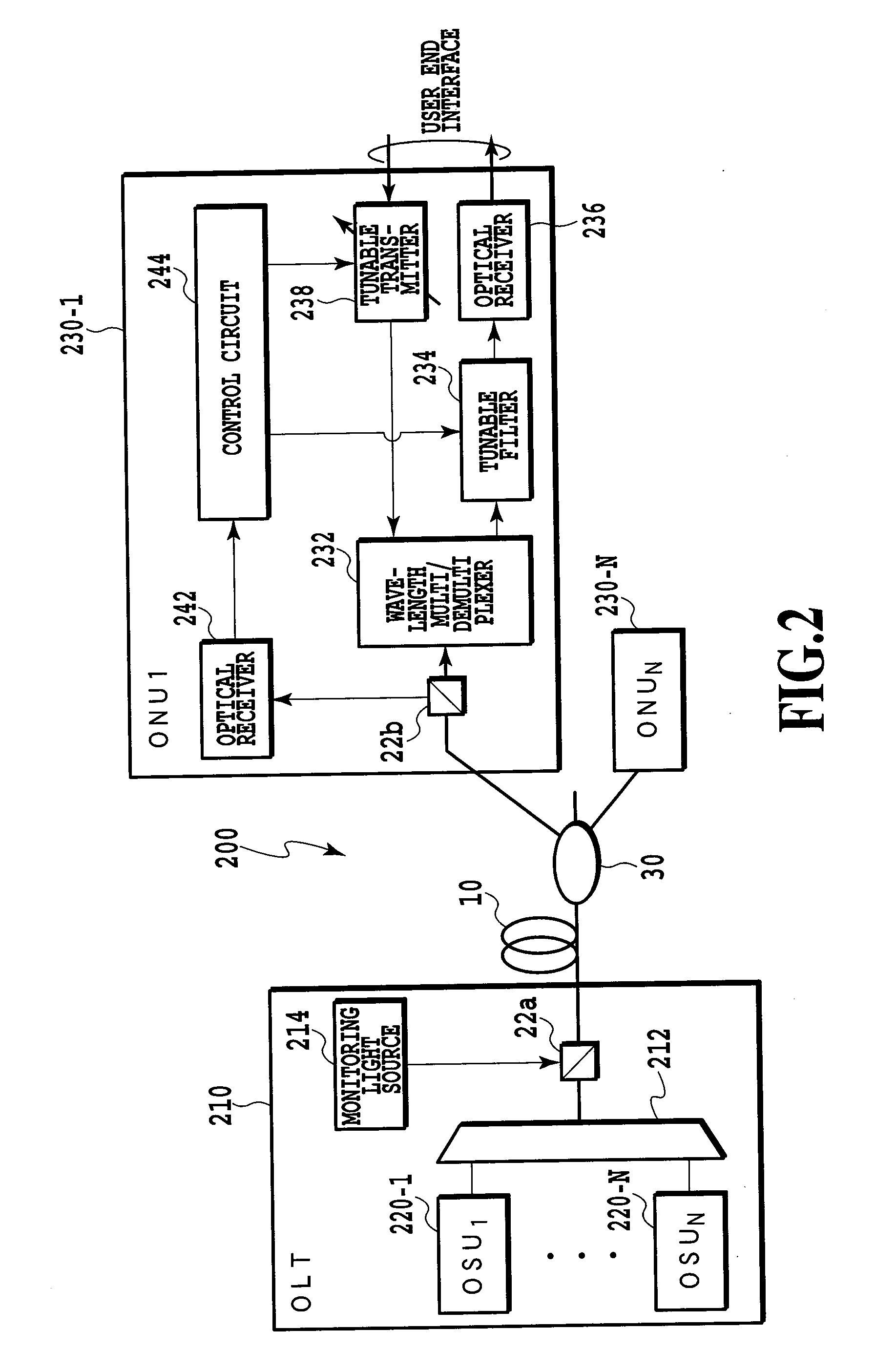
[0036]FIG. 3 shows an exemplary configuration of a star-type network using an optical TX / RX device according to the present invention. Network 300 is composed of an optical line terminal (OLT) 310 for transmitting and receiving wavelength-multiplexed signal light, an optical fiber 10 through which the signal light propagates, a power splitter 30 for combining or splitting the optical signal with 1 to N, and N optical network units (ONUs) (optical TX / RX devices) 330-1 to 330-N each transmitting and receiving optical signal.

[0037]OLT 310 comprises N optical subscriber units (OSUs) 320-1 to 320-N each transmitting and receiving signal light with an assigned wavelength, a wavelength control circuit 314 for controlling the wavelengths of signal light used for TX and RX by the OSUs, and a wavelength multi / demultiplexer 312 for multiplexing the optical signals from the OSUs an...


PUM


Abstract

According to the present invention, a star-type wavelength multiplexed communication network using optical TX / RX devices capable of assigning the wavelengths can be provided without using the monitoring light. In an embodiment of the present invention, an optical TX / RX device for transmitting and receiving a wavelength-multiplexed signal light comprises an optical receiver capable of varying the RX wavelength and an optical transmitter capable of varying the TX wavelength. The optical TX / RX device detects RX wavelengths not in use via the optical receiver, and assigns the RX wavelength of the optical receiver to one of the RX wavelengths not-in-use, and assigns the TX wavelength of the optical transmitter to a TX wavelength corresponding to the RX wavelength according to a correspondence table of TX and RX wavelengths in the memory. Then, the optical TX / RX device transmits a signal light on this TX wavelength, and detects the response on the RX wavelength. If the response is detected, communication is initiated using the assigned TX wavelength and the RX wavelength. If the response is not detected, the operation is repeated from the detection of RX wavelengths not in use to the transmission of the signal light on TX wavelength again.

Description

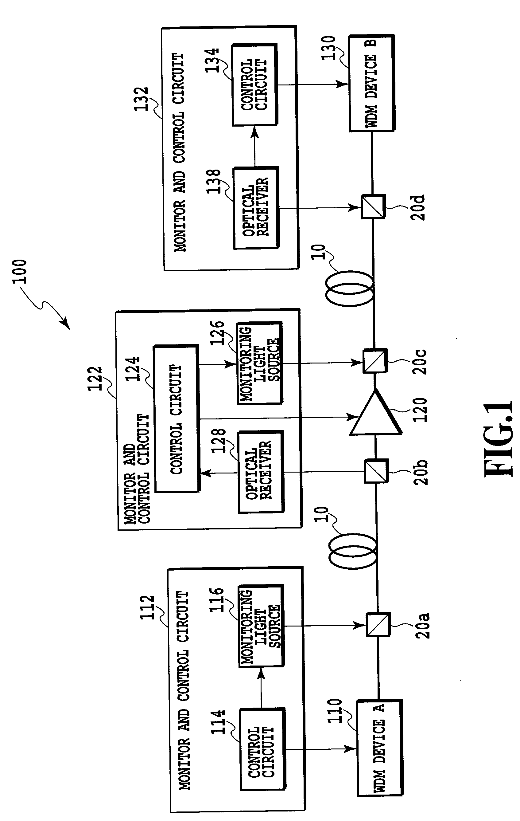
TECHNICAL FIELD[0001]The present invention relates to an optical transmitter (TX) and receiver (RX) device used for wavelength multiplexed optical communication and a star-type network using the device.BACKGROUND ART[0002]Conventionally, in a relay network using wavelength multiplexing scheme, monitoring light with a different wavelength from signal light is used to transmit wavelength information of the signal light and the like as monitoring information for monitor and control of wavelengths to be used (Patent Document 1).[0003]FIG. 1 shows an exemplary configuration for monitor and control in such relay network. As shown in the figure, in network 100, wavelength-multiplexed signal light is transmitted from WDM device A 110 to WDM device B 130 via linear optical repeater 120. In this case, monitoring information such as power, wavelengths in use, and the number of the wavelengths for signal light is transmitted from monitor and control circuit 112 to monitor and control circuit 13...

Claims


Application Information

Patent Timeline
Patent Type & Authority Applications(United States)
IPC IPC(8): H04J14/02H04B10/00H04B10/07H04B10/27H04B10/272H04B10/29H04J14/00
CPCH04B10/0793H04B10/07957H04J14/0226H04J14/025H04J14/0282H04J14/0246H04J14/0227H04B10/2581H04B10/272H04B10/40
Inventor SUZUKI, HIROOYAMADA, TAKASHIIWATSUKI, KATSUMI
Owner NIPPON TELEGRAPH & TELEPHONE CORP
Learn More