Device for fixation of bone fractures

a technology for fixing devices and bone fractures, applied in the field of sonic fusion technology, can solve the problems of not being reliable in the distribution of fixation cement within the portion of bone at the tip of the bone screw, applying to the fixation cement,

Active Publication Date: 2009-01-15
WOODWELDING +1
View PDF5 Cites 63 Cited by
  • Summary
  • Abstract
  • Description
  • Claims
  • Application Information

AI Technical Summary

Benefits of technology

[0006]An object of the invention is to define a device and a method by means of which a reliabl

Problems solved by technology

This system has the drawback that the manual pressure applied to the fixation cement varies, not only basically from application to application but also during

Method used


Image

  • Device for fixation of bone fractures
  • Device for fixation of bone fractures
  • Device for fixation of bone fractures

Examples


Embodiment Construction

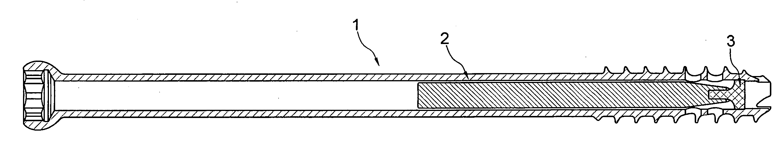
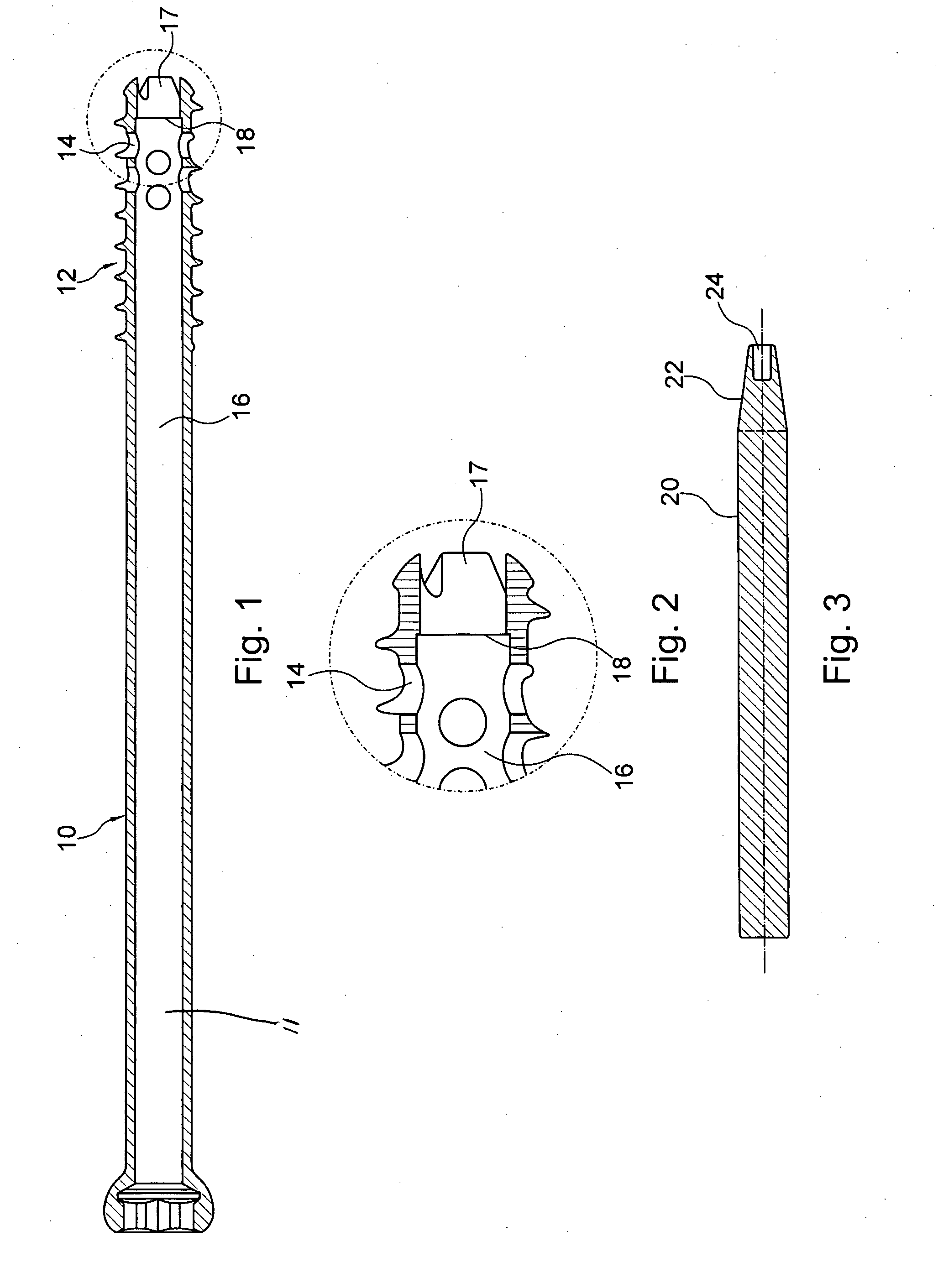
[0015]Referring now to FIG. 1 there is illustrated a bone screw 10 in accordance with the invention. The bone screw comprises a shank and a thread 12 machined in an end portion of the shank, although the thread may also cover the shank of the screw full length. In addition, the bone screw 10 is cannulated. The cannulation is provided along the longitudinal center line of the screw as a through bore 11 composed of two bore portions 16, 17. Bore portion 16 comprises a first diameter and bore portion 17 a second diameter, the first diameter being larger than the second diameter. In addition the bore portion 16 forms the main portion of through bore 11. In the preferred embodiment, just a small portion adjoining the end of the shank of the bone screw in which the thread 12 is machined is formed by the bore portion 17. The transition from the bore portion 16 to the bore portion 17 is formed by a step 18 in the bore 11. The step 18 in the bore forms an annular ridge having substantially r...


PUM


Abstract

A device and method for fixation of bone fractures has a bone screw comprising a shank with a threaded end portion, on the outer surface. The screw has a through bore with two bore portions differing in diameter. A step in the diameter is formed between these bore portions and is located within the end of the screw having the thread. This step in diameter can support a metal insert which in turn supports a polymer pin when the latter if pressurized with a sonotrode in the bone screw. Together with an applied ultrasonic vibration the pressure fluidizes the polymer pin and presses the material through holes configured in the wall of the bone screw and into surrounding bone.

Description

BACKGROUND OF THE INVENTION[0001]The invention relates in general to sonic fusion technology, it relating more particularly to a device and a method for the fixation of bone fractures, with a bone screw for augmenting within a bone.[0002]Known from U.S. Pat. No. 4,653,489 is a system wherein a fixation cement is introduced through a bone screw into a portion of a bone afflicted by osteoporosis. Femoral neck fractures as well as distal femoral fractures can be fixated by means of this device.[0003]The system in accordance with prior art comprises a bone screw having a flow cavity, i.e. an axial through bore through which bone cement can be introduced into the portion at the tip of the screw. The bone cement is advanced by a device which is releasably attached to the trailing end of the screw. This device is similar to a commercially available syringe in comprising substantially a cylindrical barrel and a plunger. The barrel forms a cavity in which the plunger is movable to and fro.[0...

Claims


Application Information

Patent Timeline
IPC IPC(8): A61B17/04A61B17/56
CPCA61B17/7098A61B17/864A61B17/846A61B17/8822A61B2017/8655A61B17/8685
Inventor DORAWA, KLAUSSCHWAGER, MANUEL
Owner WOODWELDING
Why Eureka
Try Eureka