Microscopic geometry cutting device and microscopic geometry cutting method

a cutting device and microscopic geometry technology, applied in process and machine control, process control, instruments, etc., can solve the problems of high-precision microscopic surface geometry that cannot be provided on the surface of workpieces, the cutting depth and the time for advancing and retraction of cutters is likely to be delayed. , to achieve the effect of quick control of the cutting depth of the cutter

Active Publication Date: 2009-01-22
TOSHIBA MASCH CO LTD
View PDF13 Cites 16 Cited by
  • Summary
  • Abstract
  • Description
  • Claims
  • Application Information

AI Technical Summary

Benefits of technology

[0036]In such arrangement, the piezoelectric element laminate, in which a plurality of piezoelectric elements are laminated, is used as the reciprocating stage. Acc

Problems solved by technology

Accordingly, a timing for advancement and retraction of the cutter is likely to be delayed and a highly accurate microscopic surface geometry may not be provided on the surface of the workpiece.
Accordingly, the highly accurate microscopic surface geometry cannot be provided on the surface of the w

Method used


Image

  • Microscopic geometry cutting device and microscopic geometry cutting method
  • Microscopic geometry cutting device and microscopic geometry cutting method
  • Microscopic geometry cutting device and microscopic geometry cutting method

Examples


first exemplary embodiment

Advantages of First Exemplary Embodiment

[0066]According to the first exemplary embodiment, the following advantages can be obtained.

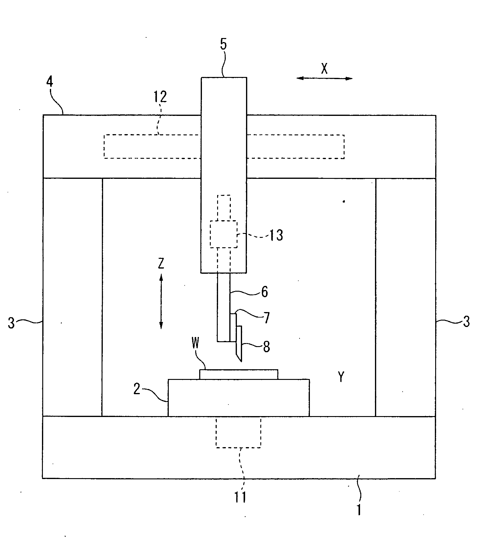
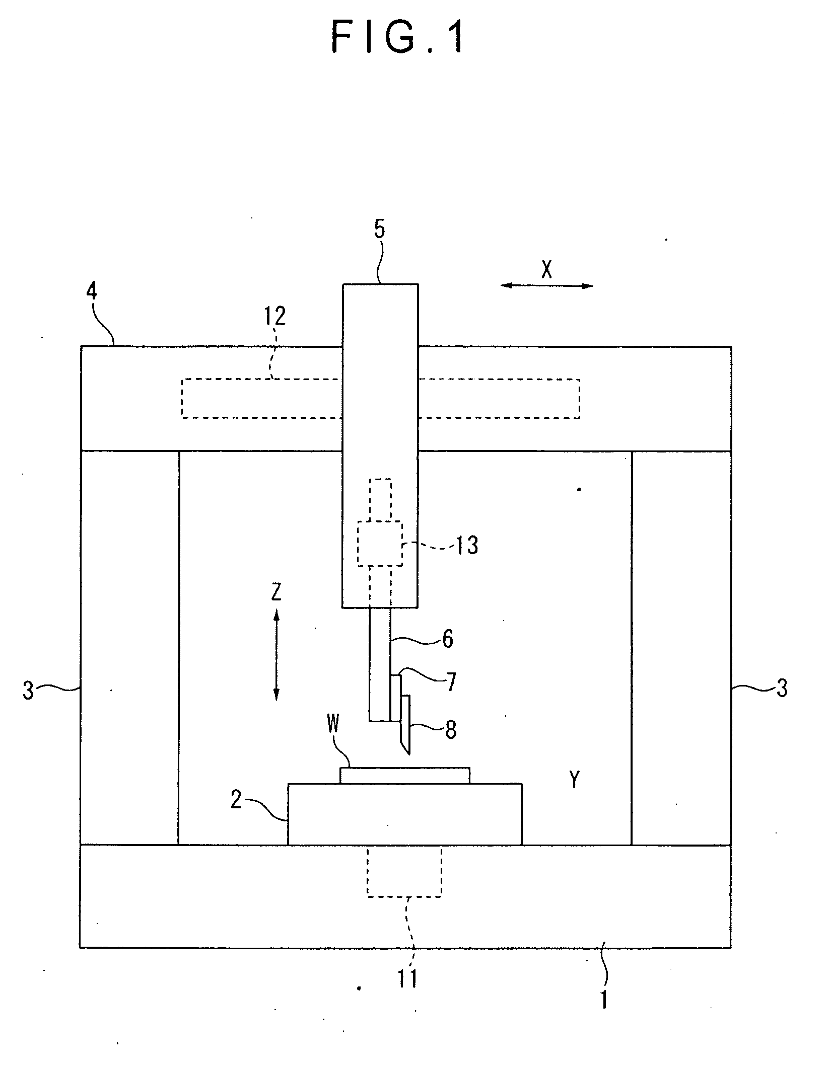
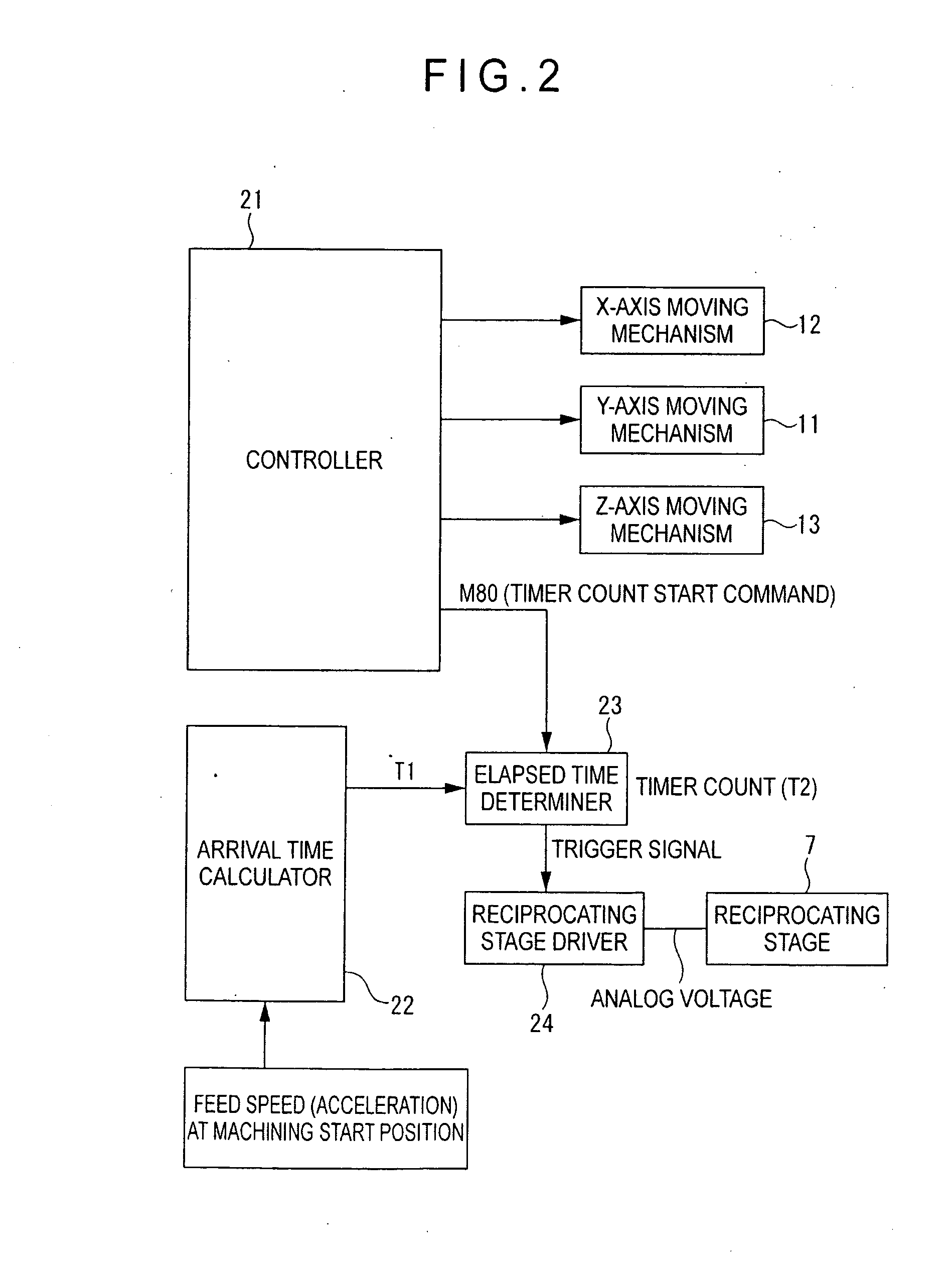
[0067](1) In the first exemplary embodiment, the elapsed time T2 is measured from when the timer count start command is output in starting the driving program, the reciprocating stage 7 is driven in response to the trigger signal output when the elapsed time T2 is coincident with the arrival time T1 preliminarily calculated by the arrival time calculator 22. Thus, the highly accurate microscopic surface geometry can be provided on the surface of the workpiece W.

[0068]Specifically, since a related art is not utilized, in which position information is detected by a position detector; a pulse signal from the position detector is counted; whether or not a counted value is coincident with a preset value is determined; and a cutting depth of a cutter is quickly changed by a tool moving mechanism by a trigger signal when the counted value and the preset value ...

second exemplary embodiment

Advantages of Second Exemplary Embodiment

[0086]According to the second exemplary embodiment, the following advantages can be obtained, in addition to the above-described advantages (1)-(3) of the first exemplary embodiment.

[0087](4) In the second exemplary embodiment, the frequency of the target track of the cutter 8 is preliminarily analyzed and the machining condition such as the most adequate feed speed is decided based on the frequency analysis result. Thus, the highly accurate microscopic geometry can be provided on the surface of the workpiece W. In other words, since an amplitude reduction of the actual movement track of the cutter 8 and phase-delay are decreased, the highly accurate microscopic geometry can be provided on the surface of the workpiece W.

[0088](5) In the machining condition deciding step according to the second exemplary embodiment, a feed speed is selected in such manner that the intrinsic frequency of a device including the reciprocating stage 7 and respecti...


PUM

PropertyMeasurementUnit
Depthaaaaaaaaaa
Frequencyaaaaaaaaaa

Abstract

A microscopic geometry cutting device includes: a controller that outputs a timer count start command in starting a driving program which controls a drive of an X-axis or a Y-axis moving mechanism; an arrival time calculator that calculates an arrival time from when the timer count start command is output till when the cutter arrives at a machining start position in accordance with relative moving speed information of the moving mechanisms and machining start position information of a workpiece W; an elapsed time determiner that determines whether an elapsed time from when the timer count start command is output is coincident with the arrival time and outputs a trigger signal when the elapsed time is coincident with the arrival time; and a reciprocating stage driver that drives the reciprocating stage in a manner that the cutter advances and retracts in a predetermined cutting depth in response to the trigger signal.

Description

BACKGROUND OF THE INVENTION[0001]1. Field of the Invention[0002]The present invention relates to a microscopic geometry cutting device and microscopic geometry cutting method for providing a microscopic asperity on a surface of a workpiece.[0003]2. Description of Related Art[0004]Conventionally, a microscopic surface cutting device and microscopic cutting method disclosed in document (JP-A-2006-123085) have been known as a device and method for providing a microscopic asperity on a surface of a workpiece.[0005]The microscopic surface cutting device includes: a first reciprocating slide mechanism; a second slide mechanism that moves for intermittent positioning in a direction orthogonal to a moving direction of the first slide mechanism; a tool moving mechanism that quickly and finely controls cutting depth of a cutter in a direction orthogonal to moving directions of the first and second slide mechanisms; and a position detector that generates a pulse signal in accordance with a mov...

Claims


Application Information

Patent Timeline
IPC IPC(8): B26D5/00
CPCB23B29/125B23B2260/108B23B2265/16G05B19/4163Y10T409/50082B26D3/085Y10T409/506232Y10T409/504428Y10T409/500164G05B2219/41344Y10T83/0341Y10T83/141B23Q15/013G05B19/00G05B19/182G05B2219/45044G06F17/142
Inventor KIMURA, SEIJIKONDO, SUMIHISA
Owner TOSHIBA MASCH CO LTD
Why Eureka
Try Eureka