Electric fan module and airflow conduction structure thereof

a technology of electric fan and conduction structure, which is applied in the direction of electrical apparatus contruction details, machines/engines, liquid fuel engines, etc., can solve the problems of poor heat dissipation effect, and low efficiency or even operational interruption, so as to reduce wind resistance and promote heat dissipation efficiency

Inactive Publication Date: 2009-01-22
TOPOWER COMP IND CO LTD
View PDF5 Cites 13 Cited by
  • Summary
  • Abstract
  • Description
  • Claims
  • Application Information

AI Technical Summary

Benefits of technology

[0005]The primary objective is to guide the central airflow to fan blades to overcome the conventional problem that a vacuum state or wind shear is created at the central region during the rotation of an electric fan and to reduce wind resistance and promote heat dissipation efficiency.

Problems solved by technology

Heat may induce low efficiency or even operational interruption.
However, the axial portion of the electric fan is a plane, which is apt to create wind resistance or a vacuum state and results in a poor heat dissipation effect.
However, due to the extended fan blades, the axial portion has an uneven surface, which is apt to create wind resistance and wind shear and result in a poor heat dissipation effect.

Method used


Image

  • Electric fan module and airflow conduction structure thereof
  • Electric fan module and airflow conduction structure thereof
  • Electric fan module and airflow conduction structure thereof

Examples


Embodiment Construction

[0011]Below, the technical contents of the present invention are to be described in detail in cooperation with the drawings.

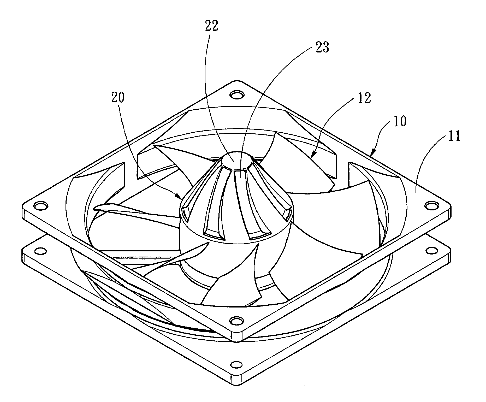
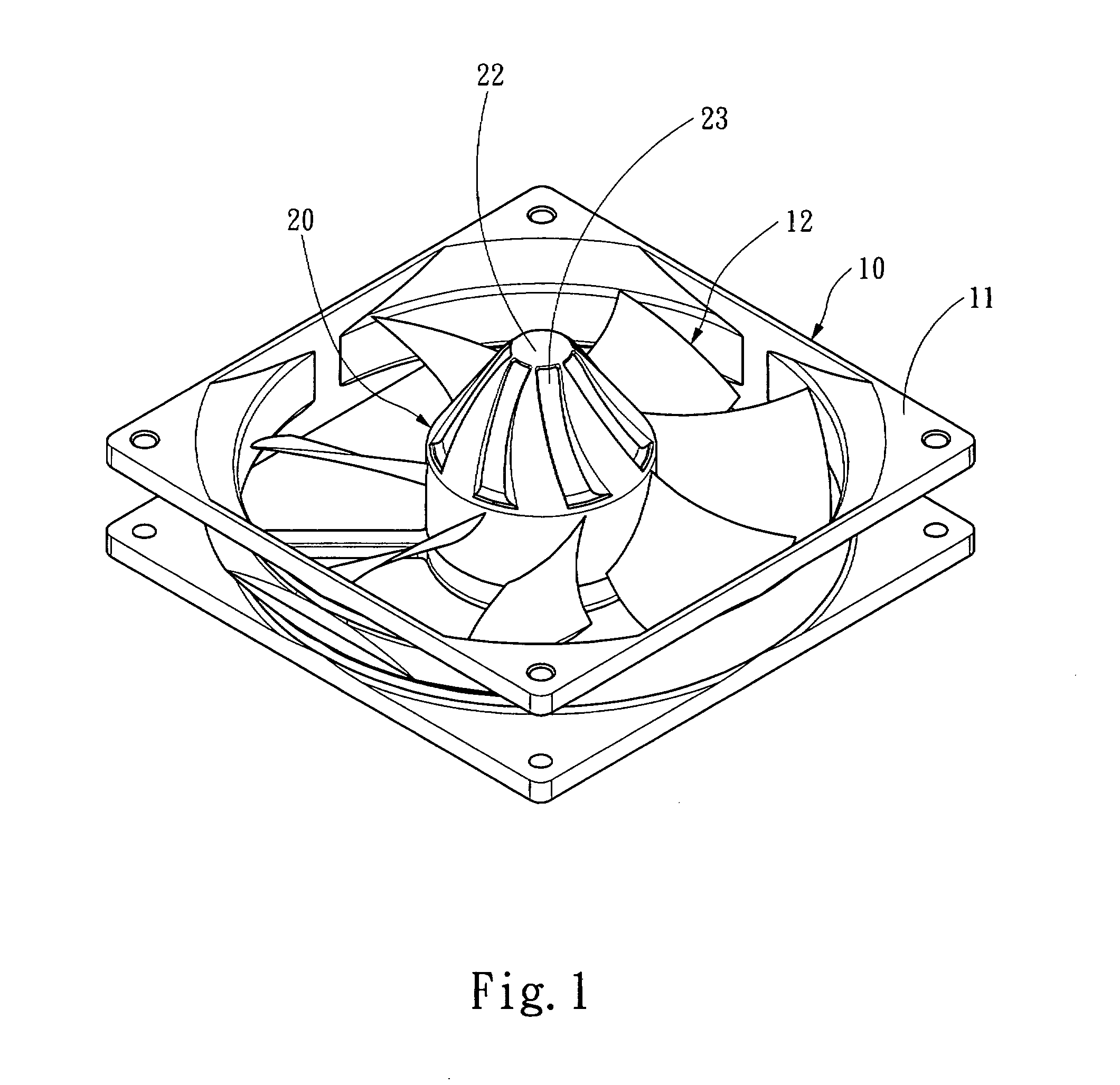
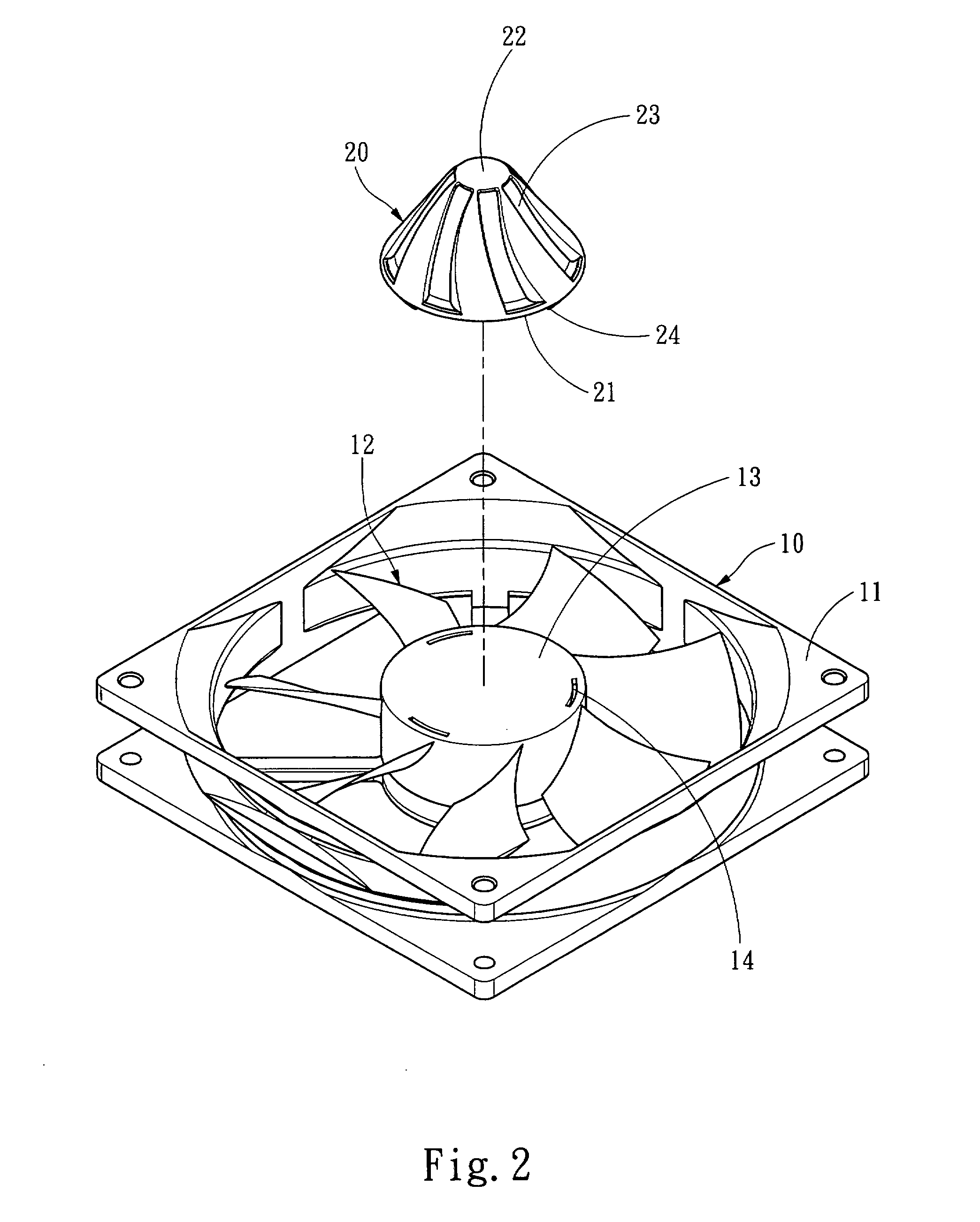
[0012]Refer to FIG. 1 and FIG. 2 a perspective view and an exploded view respectively schematically showing the appearance and structure according to the present invention. The present invention includes an electric fan 10. The electric fan 10 has a casing 11 and a fan blade assembly 12. The fan blade assembly 12 is coupled to an airflow conduction body 20. The airflow conduction body 20 has a first end face 21 and a second end face 22, and the first end face 21 is greater than the second end face 22. The fan blade assembly 12 has a central portion 13 corresponding to the first end face 21, and the area of the central portion 13 is identical to the area of the first end face 21. The airflow conduction body 20 has at least one airflow conduction groove 23 axially arranged between the first and second end faces 21 and 22. In the embodiments shown in the drawings,...


PUM


Abstract

The present invention discloses an electric fan module and an airflow conduction structure thereof, wherein the airflow conduction structure is coupled to an electric fan and guides the central airflow to fan blades to reduce wind resistance and wind shear. The airflow conduction structure has an airflow conduction body and at least one airflow conduction groove arranged axially on the airflow conduction body. The airflow conduction body has a first end face and a second end face, and the first end face is greater than the second end face. The airflow conduction grooves are arranged between the first and second end faces.

Description

FIELD OF THE INVENTION[0001]The present invention relates to an electric fan module and an airflow conduction structure thereof, particularly to an electric fan module and an airflow conduction structure thereof, wherein the heat dissipation efficiency is promoted via guiding the central airflow to the fan blades.BACKGROUND OF THE INVENTION[0002]There are everywhere electronic devices in our living and working environments. An electronic device is formed of many electronic elements, which generate heat during operation. Heat may induce low efficiency or even operational interruption. Therefore, a heat-dissipation device is usually arranged above or near a heat-generating electronic element to fast take away heat and decrease the temperature of the electronic element so that the electronic element can operate normally. The manufacturers usually increase the heat-dissipation efficiency of an electric fan via modifying the structures of the electric fan casing or fan blades or via incr...

Claims


Application Information

Patent Timeline
Patent Type & Authority Applications(United States)
IPC IPC(8): F03B3/12
CPCF04D25/0613H05K7/20172F04D29/441F04D29/329F05D2250/51
Inventor CHEN, MICHAEL
Owner TOPOWER COMP IND CO LTD
Why Eureka
Try Eureka