Multi-lumen catheter assembly and method of providing relative motion thereto

a multi-lumen catheter and assembly technology, applied in the field of apparatus and method for using a multi-lumen catheter assembly, can solve the problem of difficulty for users to move multiple structures in different directions

Inactive Publication Date: 2009-01-22
THE CLEVELAND CLINIC FOUND
View PDF15 Cites 114 Cited by
  • Summary
  • Abstract
  • Description
  • Claims
  • Application Information

AI Technical Summary

Benefits of technology

[0007]In an embodiment of the present invention, a method of providing relative motion to a multi-lumen catheter assembly is described. An outer catheter member having a longitudinal axis and longitudinally spaced proximal and distal outer catheter ends with a first lumen defined therebetween is provided. An intermediate catheter member is at least partially located within the first lumen. The intermediate catheter member has longitudinally spaced proximal and distal intermediate catheter ends with a second lumen defined therebetween. An inner catheter member is at least partially located within the second lumen. The inner catheter member has longitudinally spaced proximal and distal inner catheter ends. A handle is connected to the proximal outer catheter end, the proximal intermediate catheter end, and the proximal inner catheter end. The relative position of the outer and inner catheter members is maintained. Movement of the intermediate catheter member relative to the outer and inner catheter members is provided.

Problems solved by technology

However, it can be difficult for a user to move multiple structures in different directions, possibly at different rates of motion, while monitoring conditions at the surgery site through remote viewing devices.

Method used


Image

  • Multi-lumen catheter assembly and method of providing relative motion thereto
  • Multi-lumen catheter assembly and method of providing relative motion thereto
  • Multi-lumen catheter assembly and method of providing relative motion thereto

Examples


Embodiment Construction

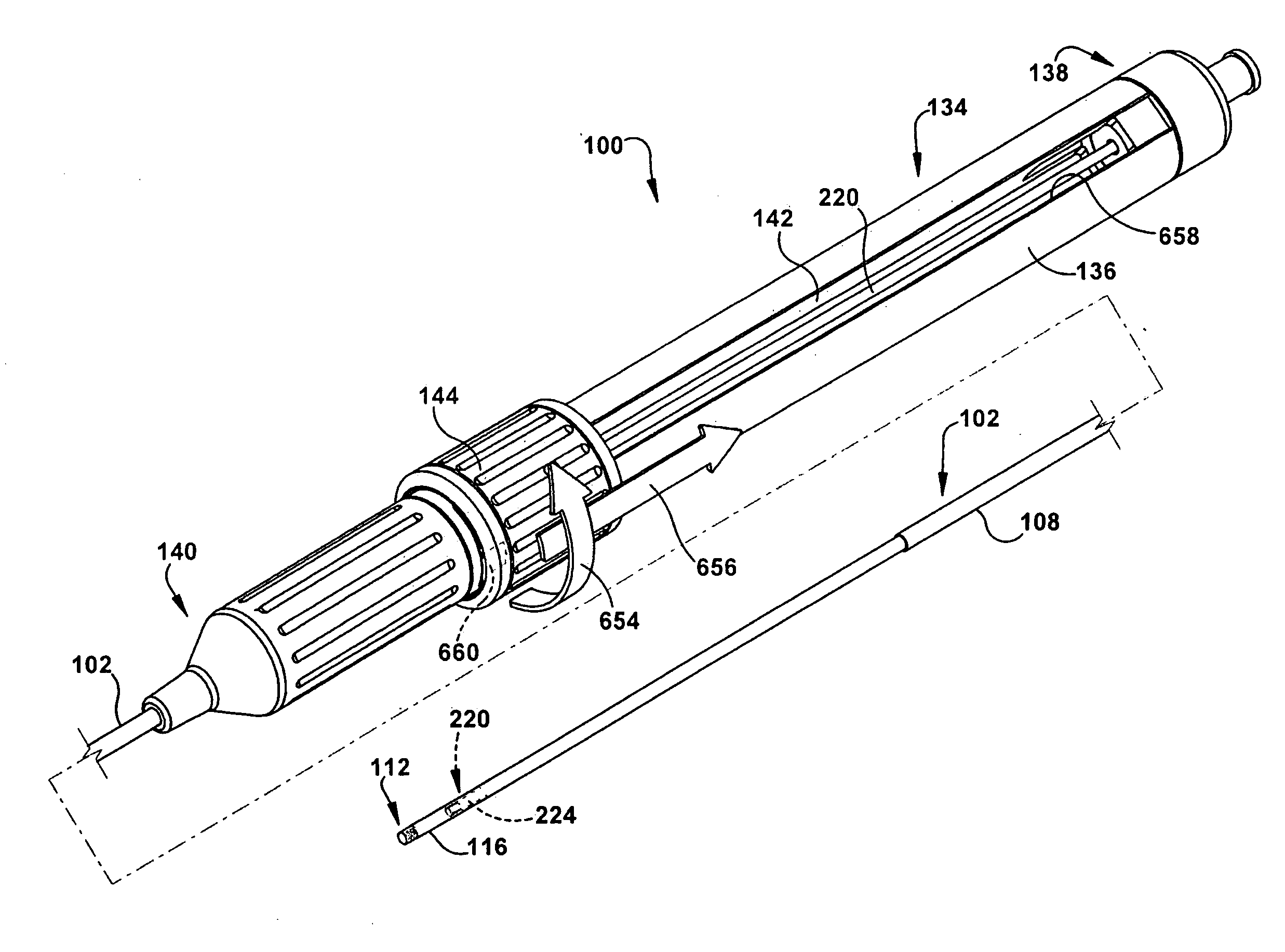
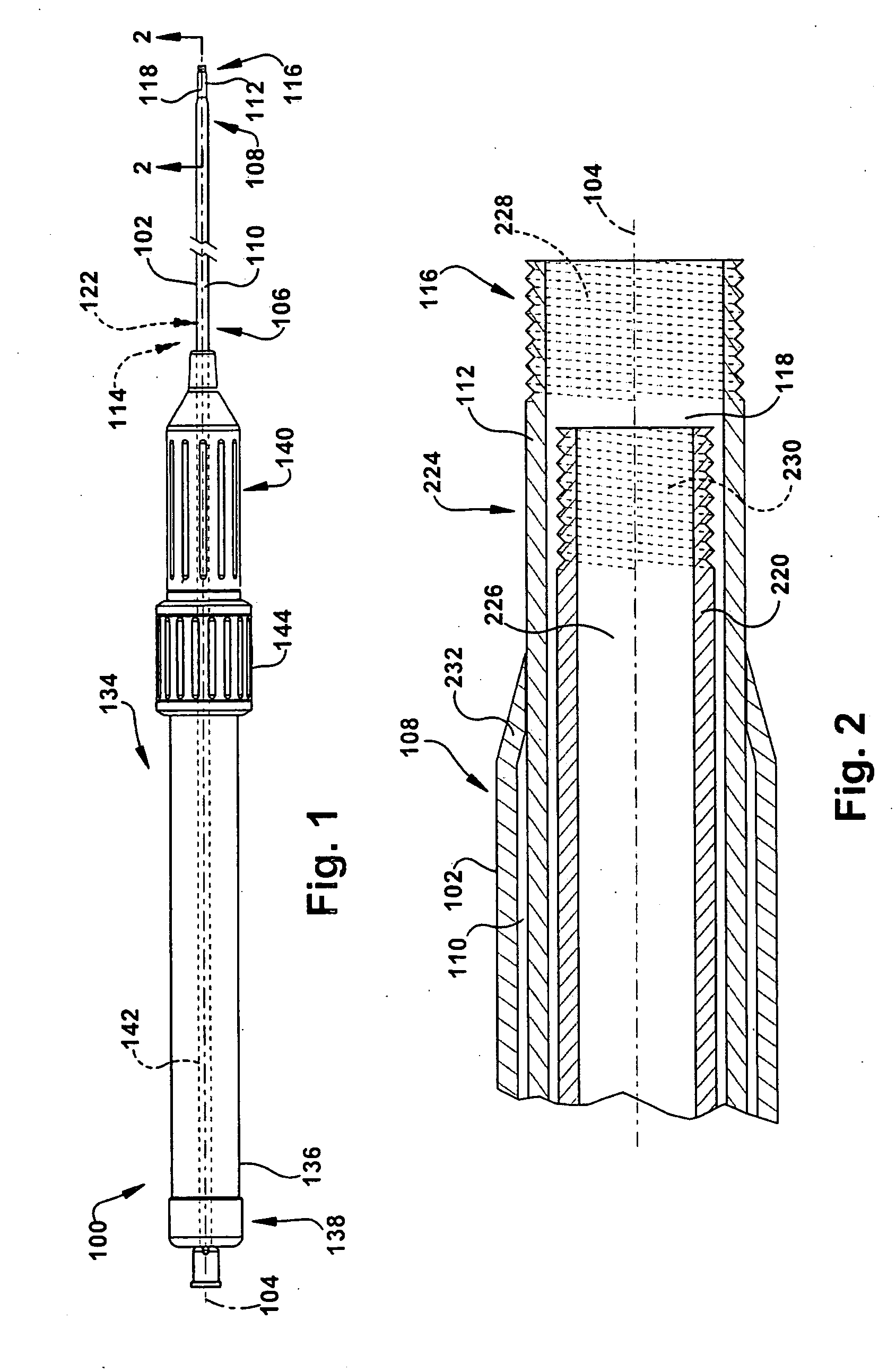
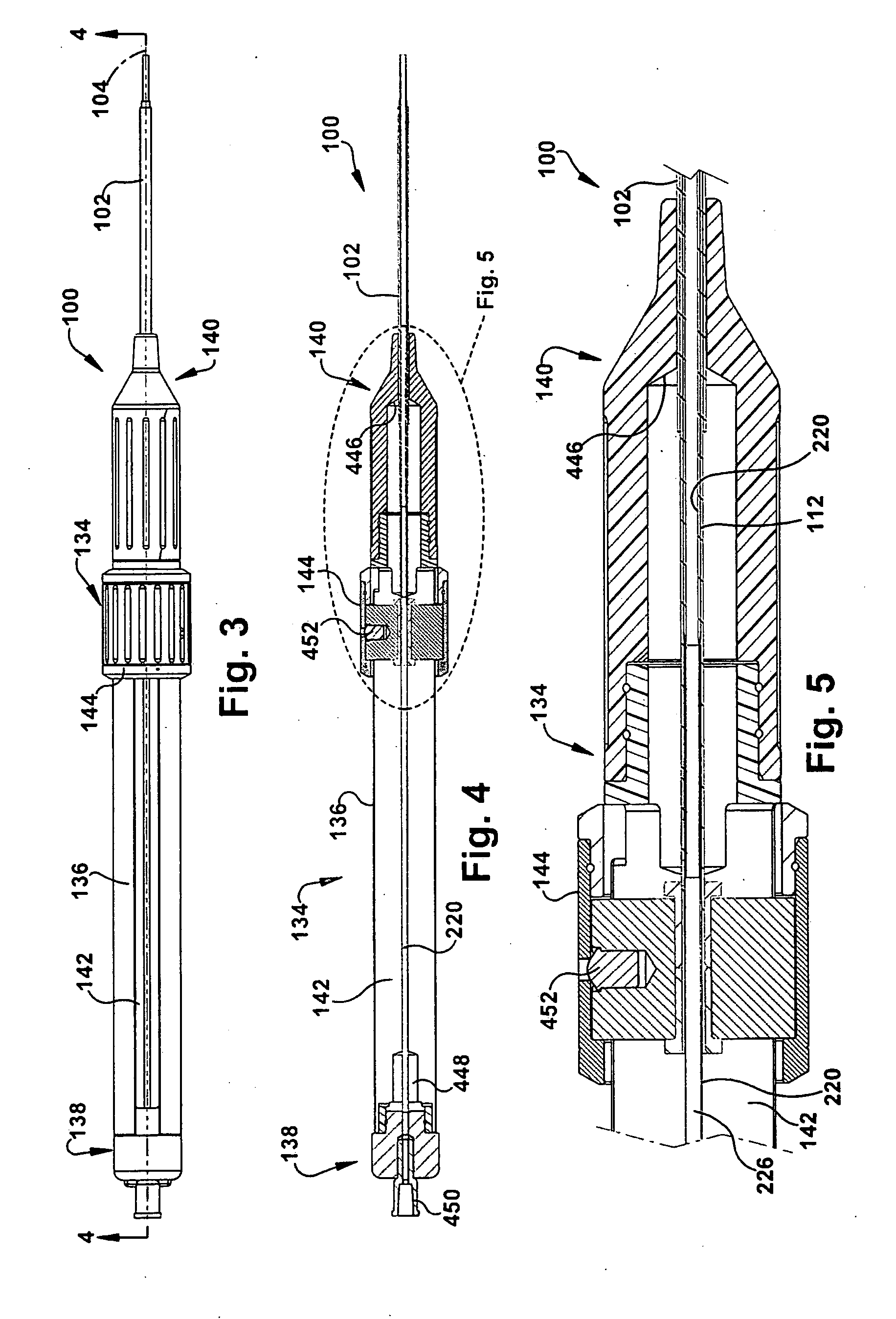
[0017]In accordance with the present invention, FIG. 1 depicts a schematic side view of a multi-lumen catheter assembly 100. An outer catheter member 102 has a longitudinal axis 104 and longitudinally spaced proximal and distal outer catheter ends 106 and 108, respectively, with a first lumen 110 defined therebetween. The outer catheter member 102 may be dimensioned as desired for use in a particular application of the present invention. Like many longitudinally oriented structures described herein, only a portion of the length of the outer catheter member 102 is shown, for ease of depiction.

[0018]An intermediate catheter member 112 is at least partially located within the first lumen 110. The intermediate catheter member has longitudinally spaced proximal and distal intermediate catheter ends 114 (hidden within the outer catheter member 102 in this view) and 116, respectively, with a second lumen 118 defined therebetween.

[0019]An inner catheter member 220 is at least partially loca...


PUM


Abstract

A handle for providing relative motion to a multi-lumen catheter assembly includes an elongated handle body having a longitudinal axis. The handle body has longitudinally spaced proximal and distal handle ends. An outer catheter chuck is connected to the distal handle end and is adapted to receive an outer catheter member. An inner catheter chuck is connected to the proximal handle end and is adapted to receive an inner catheter member. A handle actuator is movably connected to the handle body. The handle actuator is adapted to receive an intermediate catheter member and to move the intermediate catheter member relative to the inner and outer catheter members. The intermediate catheter is at least partially interposed between the inner and outer catheter.

Description

RELATED APPLICATION[0001]This application claims the benefit of U.S. Provisional Patent Application Ser. No. 60 / 959,736, filed Jul. 16, 2007 which is incorporated herein by reference.TECHNICAL FIELD[0002]The present invention relates to an apparatus and method for use of a multi-lumen catheter assembly and, more particularly, to a handle for providing relative motion to a multi-lumen catheter assembly and a method of using the handle.BACKGROUND OF THE INVENTION[0003]In many minimally invasive surgical procedures, such as percutaneous procedures, a catheter is inserted into a patient's body to facilitate remote manipulation of surgical tools at a surgery site within the patient. For example, a user may desire to deploy an intraluminal prosthesis within a patient's vasculature, possibly with the assistance of an apparatus such as that disclosed in the commonly assigned U.S. patent application Ser. No. 11 / 601,075, filed Nov. 16, 2006 for APPARATUS AND METHOD FOR DELIVERING LINED INTRAL...

Claims


Application Information

Patent Timeline
Patent Type & Authority Applications(United States)
IPC IPC(8): A61M25/01
CPCA61M25/0097A61M2025/0006A61M2025/0004A61M25/0136
Inventor KHOSLA, RAJESH K.CHRISTIAN, STEVE
Owner THE CLEVELAND CLINIC FOUND
Why Eureka
Try Eureka