Controlled Porosity Stent

Active Publication Date: 2009-01-22
MEDTRONIC VASCULAR INC
View PDF43 Cites 42 Cited by
  • Summary
  • Abstract
  • Description
  • Claims
  • Application Information

AI Technical Summary

Problems solved by technology

However, this technique requires that the layer of alloyed material be joined to a base st

Method used


Image

  • Controlled Porosity Stent
  • Controlled Porosity Stent
  • Controlled Porosity Stent

Examples


Embodiment Construction

[0015]The invention will now be described by reference to the drawings wherein like numbers refer to like structures.

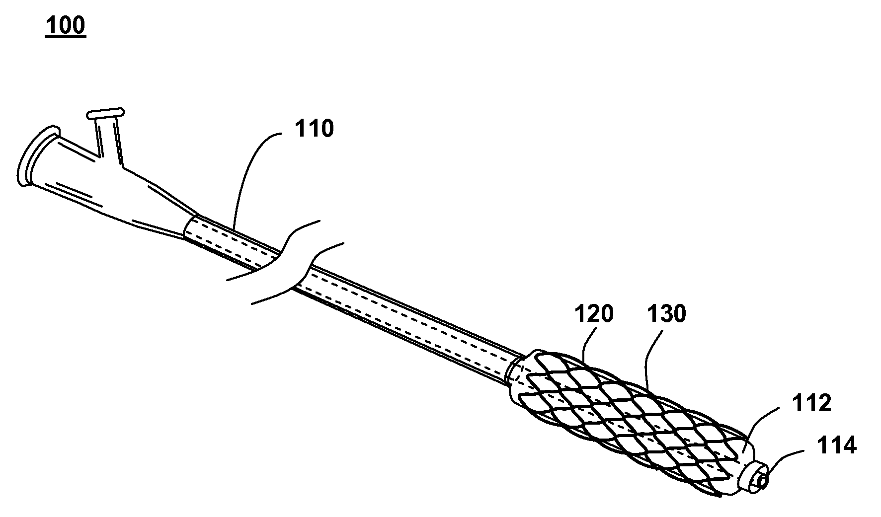
[0016]FIG. 1 shows an illustration of a system for treating a vascular condition, comprising a stent coupled to a catheter, in accordance with one embodiment of the present invention at 100. Stent with catheter 100 includes a stent 120 coupled to a delivery catheter 110. Stent 120 includes a stent framework 130. In one embodiment, at least one drug coating, or a drug-polymer layer, is applied to a surface of the stent framework.

[0017]Insertion of stent 120 into a vessel in the body helps treat, for example, heart disease, various cardiovascular ailments, and other vascular conditions. Catheter-deployed stent 120 typically is used to treat one or more blockages, occlusions, stenoses, or diseased regions in the coronary artery, femoral artery, peripheral arteries, and other arteries in the body. Treatment of vascular conditions may include the prevention or correction o...


PUM

PropertyMeasurementUnit
Compositionaaaaaaaaaa
Therapeuticaaaaaaaaaa
Heataaaaaaaaaa

Abstract

A method of manufacturing a stent includes forming a stent blank including a predetermined alloy composition, the alloy composition including at least base element and at least one sacrificial element and forming a stent framework from the stent blank. The method further includes removing at least a portion of the sacrificial element and forming at least one pore based on the removal. A method of manufacturing a vascular treatment system includes forming a stent blank including a predetermined alloy composition including at least one base element and at least one sacrificial element. The method further includes forming a stent framework and removing at least a portion of the sacrificial element. The method also includes forming at least one pore based on the removal, bending the stent framework to a delivery shape, and attaching the bent stent framework including the formed pores to a catheter.

Description

TECHNICAL FIELD[0001]This invention relates generally to medical devices for treating vascular problems, and more particularly to a stent with a controlled alloy.BACKGROUND OF THE INVENTION[0002]Vascular stents are commonly used to restore patency to a myriad of vessels. These stents are often deployed with a drug applied to the surface, either directly, or with a polymer. It is desirable to increase the volume of drug carried upon the stent, and previous solutions have provided for the depots, channels, pores, or similar surface modifications in an exterior surface of the stent. Typically, these modifications result from the application of a mechanical or chemical force to the surface of the stent. For example, some surface modifications are stamped onto the surface, while other stents receive a chemical bath to etch a pattern, such as with lithography.[0003]Another prior solution includes attaching a layer of an alloyed material to a base stent, and then applying a dealloying proc...

Claims


Application Information

Patent Timeline
IPC IPC(8): A61F2/06
CPCA61F2/91A61F2250/0067A61F2250/0068A61L31/022Y10T29/49995A61F2210/0076Y10T29/49885Y10T29/49996A61L31/146
Inventor BIRDSALL, MATTHEW J.ALLEN, JEFFREY W.
Owner MEDTRONIC VASCULAR INC
Why Eureka
Try Eureka