Road gradient estimating system
- Summary
- Abstract
- Description
- Claims
- Application Information
AI Technical Summary
Benefits of technology
Problems solved by technology
Method used
Image
Examples
first embodiment
[0043]A first embodiment of the present invention will be hereinafter explained with reference to the drawings. According to the embodiment, a road gradient estimating system of the present invention is applied to a vehicle driving / braking force control system.
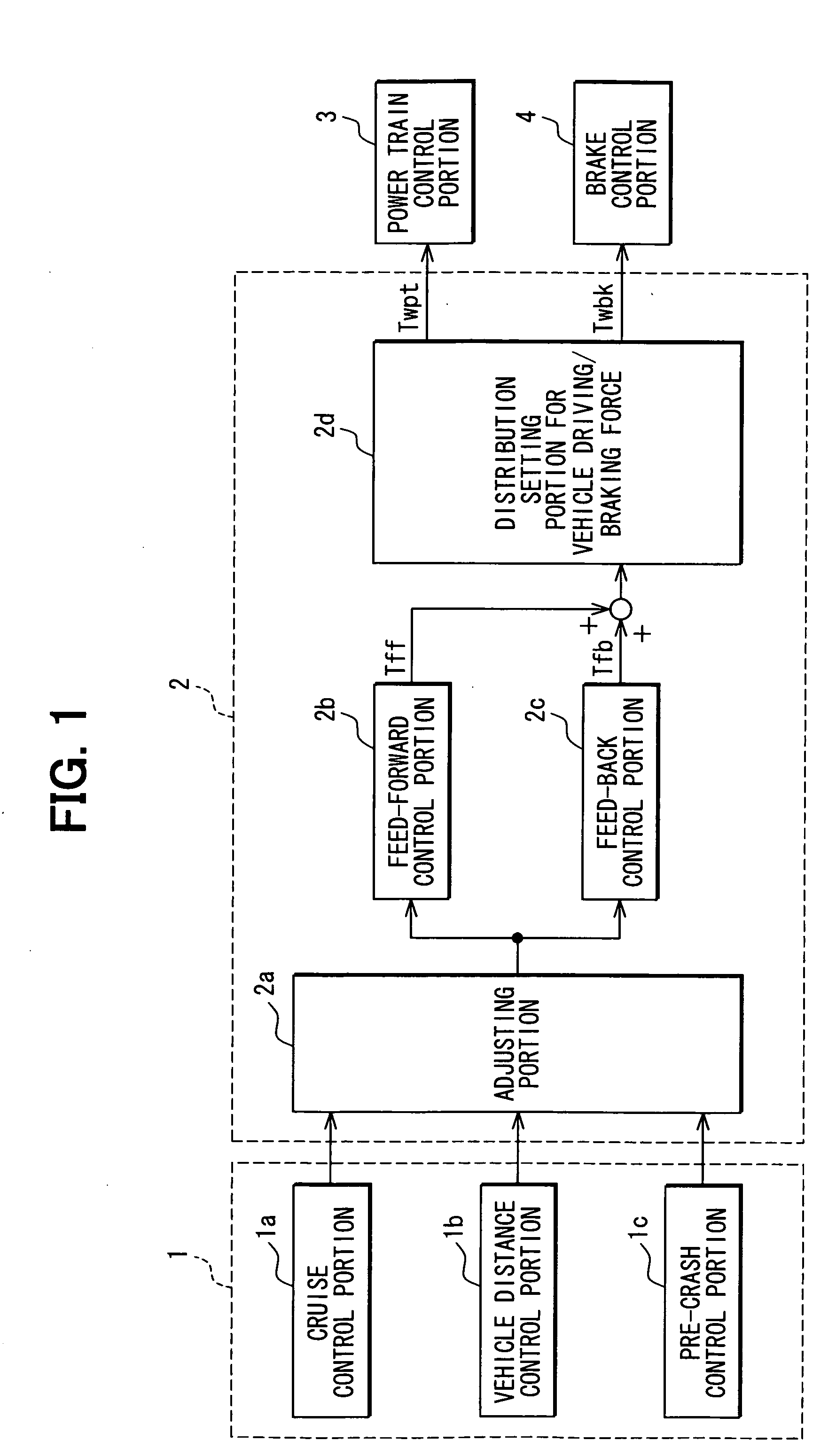
[0044]FIG. 1 is a block diagram schematically showing the vehicle driving / braking force control system. As shown in FIG. 1, the vehicle driving / braking force control system has an acceleration demanding portion 1, a control portion 2 for acceleration in a vehicle longitudinal direction, a power train control portion 3, and a brake control portion 4.
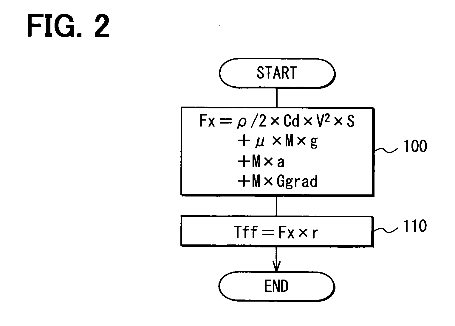
[0045]The acceleration demanding portion 1, which outputs an acceleration demanding signal depending on a vehicle condition, has a cruise control portion 1a, a vehicle distance control portion 1b, and a pre-crash control portion 1c. More exactly, the cruise control portion 1a outputs a demanding signal for acceleration, which is necessary to control a vehicle speed at a constant spe...
second embodiment
[0084]A second embodiment of the present invention will be explained. According to the second embodiment, a map for setting the limiting value with regard to the rate-of-change of the road gradient is changed, which differs from the first embodiment. The remaining portions are the same to the first embodiment. Therefore, a different portion will be explained.
[0085]FIG. 8 is an enlarged map showing a relation between the vehicle speed and the acceleration corresponding value for the limiting value with regard to the rate-of-change for the road gradient, which is memorized in the rate-of-change calculating portion 10. As shown in FIG. 8, a map for a range of vehicle low speed is added to the map shown in FIG. 4.
[0086]When the vehicle starts to move on an uphill slope (or a downhill slope) having a road gradient “θ”, angle of vehicle inclination will be changed during a period from a starting point of a front wheel (the front wheel starts to go up or go down the slope) to an ending poi...
third embodiment
[0093]A third embodiment of the present invention will be explained. According to the third embodiment, manners for setting the limiting value for the rate-of-change of the road gradient and limiting value for the road gradient are changed from the first embodiment. The remaining portions are the same to the first embodiment. Therefore, a different portion will be explained.
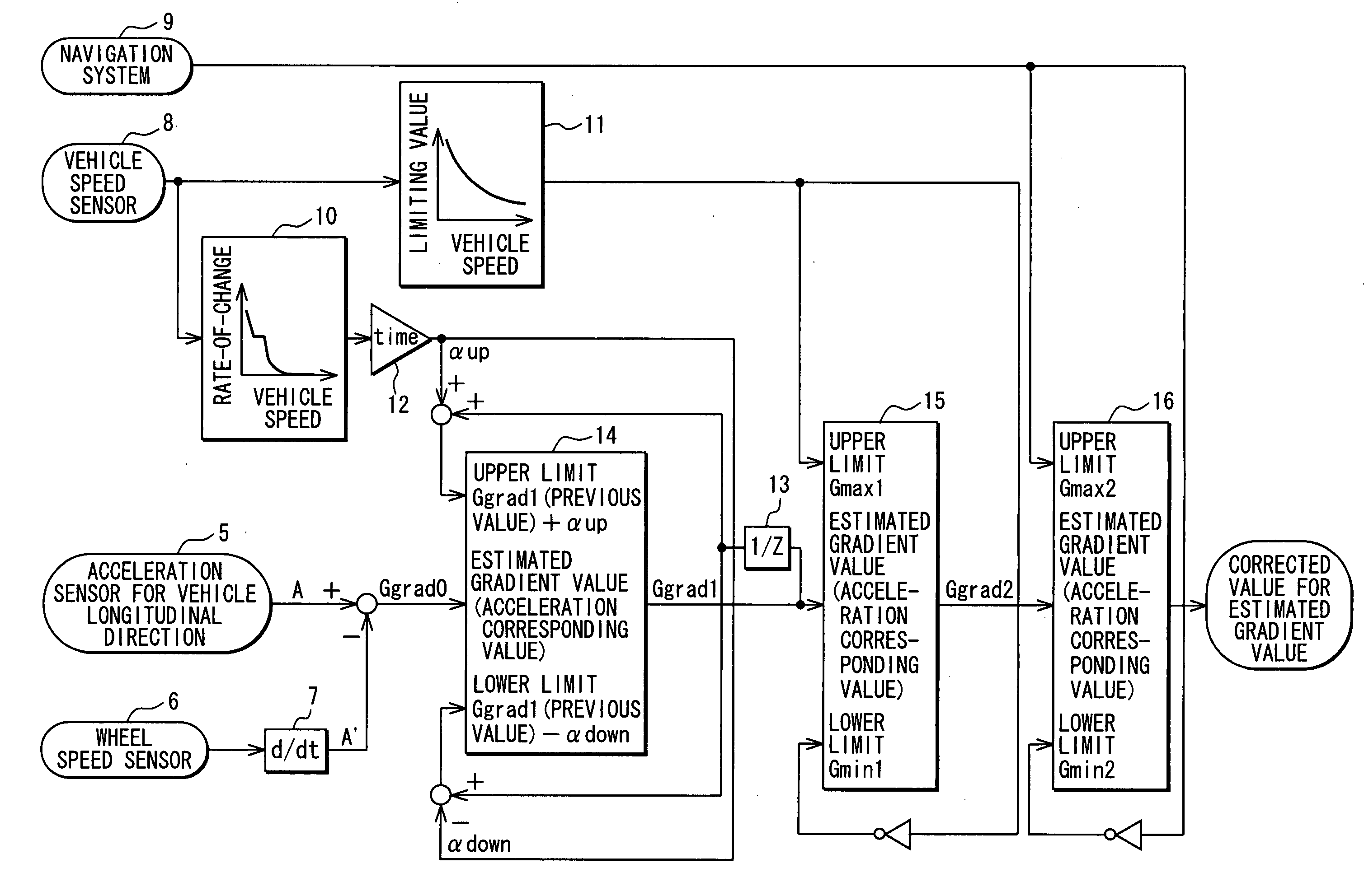
[0094]FIG. 10 is a block diagram schematically showing a road gradient estimating system according to the third embodiment. The road gradient estimating system of this embodiment calculates the acceleration corresponding value “Ggrad0” for the estimated gradient value in the conventional manner. Then, the road gradient estimating system compares the acceleration corresponding value “Ggrad0” with acceleration corresponding values for an upper limit and / or a lower limit of the estimated gradient value, which is decided by a limiting value for rate-of-change of the road gradient or a limiting value for the road grad...
PUM
 Abstract
Description
Claims
Application Information
 - R&D
- Intellectual Property
- Life Sciences
- Materials
- Tech Scout
- Unparalleled Data Quality
- Higher Quality Content
- 60% Fewer Hallucinations
Browse by: Latest US Patents, China's latest patents, Technical Efficacy Thesaurus, Application Domain, Technology Topic, Popular Technical Reports.
© 2025 PatSnap. All rights reserved.Legal|Privacy policy|Modern Slavery Act Transparency Statement|Sitemap|About US| Contact US: help@patsnap.com


