
Seismic support and reinforcement systems

a technology of seismic support and reinforcement system, applied in the direction of girders, machine supports, building repairs, etc., can solve the problems of not meeting current uniform building code (ubc) standards, many types of buildings may be heavily damaged, and the transfer mechanism is likely to be substandard, so as to eliminate or lessen dependence, the effect of simple and inexpensive, reliabl

Inactive Publication Date: 2009-01-29
DEANS BRIAN W +1
View PDF19 Cites 6 Cited by
  • Summary
  • Abstract
  • Description
  • Claims
  • Application Information

AI Technical Summary

Benefits of technology

[0018]In another aspect of the invention, one or more retro-washer embodiments are provided to replace existing cut or plate washers that anchor the ledger to the wall. These retro-washers provide support for the full length of the washer. The retro-washers are manufactured in varying lengths to accommodate different sized ledgers. The wider part of the angle-iron is drilled with at least two holes, with one hole an inch closer to the center of the washer to allow for varying bolt locations and allow for the washer to extend closest to the bottom of the sheathing. When a retro washer cannot be installed because the bolt is too close to the plywood then this washer may not be necessary anyway. In most embodiments, the retro-washers are provided with an outwardly extending flange. These flanges project out from the ledger and supply the strength that distributes force along the full length of the retro-washer when the original nut is replaced on the bolt. These embodiments are essentially upgraded washers that are designed to stop a ledger from splitting along the natural grain line that intersects the hole drilled for anchoring the ledger to the wall. The retro-washers are designed to replace existing cut washers or plate washers. The size and length of the retro washers will vary depending on the size of the ledger and the structural engineer specifications based on individual building conditions.
[0041]Another object of the invention is to provide seismic connections of the type described that either eliminates or lessens dependence on the roof, ceiling or floor plywood diaphragm perimeter nailing into the ledger that bolts onto the concrete wall at the outside perimeter of the building at the roof line and / or at wood floor connections to concrete walls.

Problems solved by technology

Many types of buildings may be heavily damaged by seismic movement, high winds and other natural disasters.
On older buildings, the transfer mechanisms are likely to be substandard either because of design deficiencies, installation shortcomings, or both, and thus are not up to current Uniform Building Code (UBC) standards.
Aside from seismic and wind forces, a common roof failure results from a build-up of rain or water from pipe leakages because of clogged roof drains or snow build-up.
When this occurs, roof collapse is often the result.
Another contributing factor in roof collapse is improper placement of anchor bolts that connect the walls to a ledger that is bolted to the inside of the wall at the roof level and subsequently to the roof plywood with nails.
Factors that exacerbate the aforementioned splitting are oversized drilling of bolt holes which, when combined with nuts that are over-tightened, may cause the (round) cut washer to bend inward at the center and exert force that causes the upper portion of the wooden ledger to separate from the lower portion.
A similar vulnerability exists where a concrete column using a prefabricated metal saddle for anchoring a GLB has been poorly installed (i.e., poor pouring, casting of the column).
When installed on a GLB that may be 24 inches or more in height, the connection is inadequate by current building codes.
In addition, when the holes drilled in the GLB for anchorage to the aforementioned GLB beam seat are oversized, this makes the edge of the drilled hole even closer to the bottom of the GLB.
Also, as is often the case, when these saddle connectors are installed out of level either side to side or end for end, this already questionable installation is worsened.
This is a system deficiency that usually occurs during a seismic event.
The aforementioned movement results in loosening of the nails that are critical to the structural integrity of the roof diaphragm system.
These purlin straps are usually anchored to purlins using only nails, and are not designed to provide vertical counterforce either upward or downward, even when installed properly.

Method used


Image

  • Seismic support and reinforcement systems
  • Seismic support and reinforcement systems
  • Seismic support and reinforcement systems

Examples


Embodiment Construction

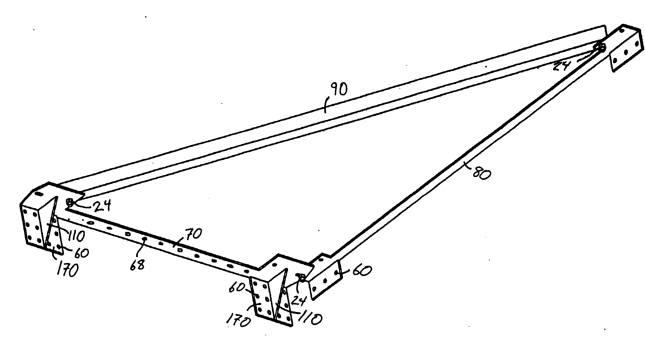
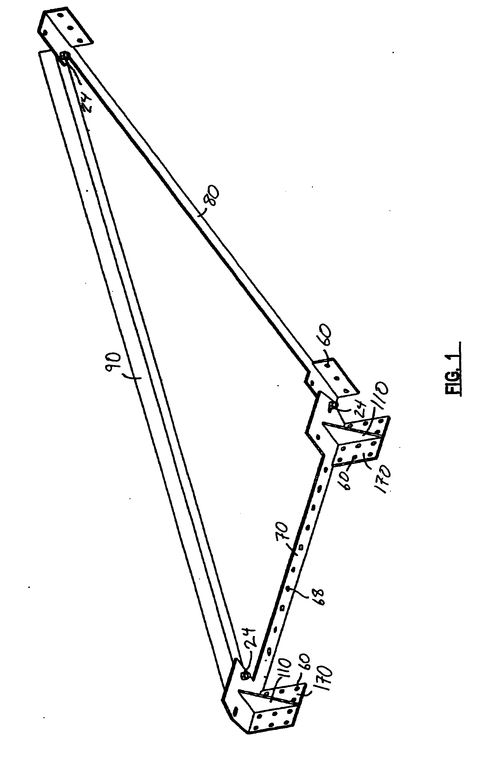
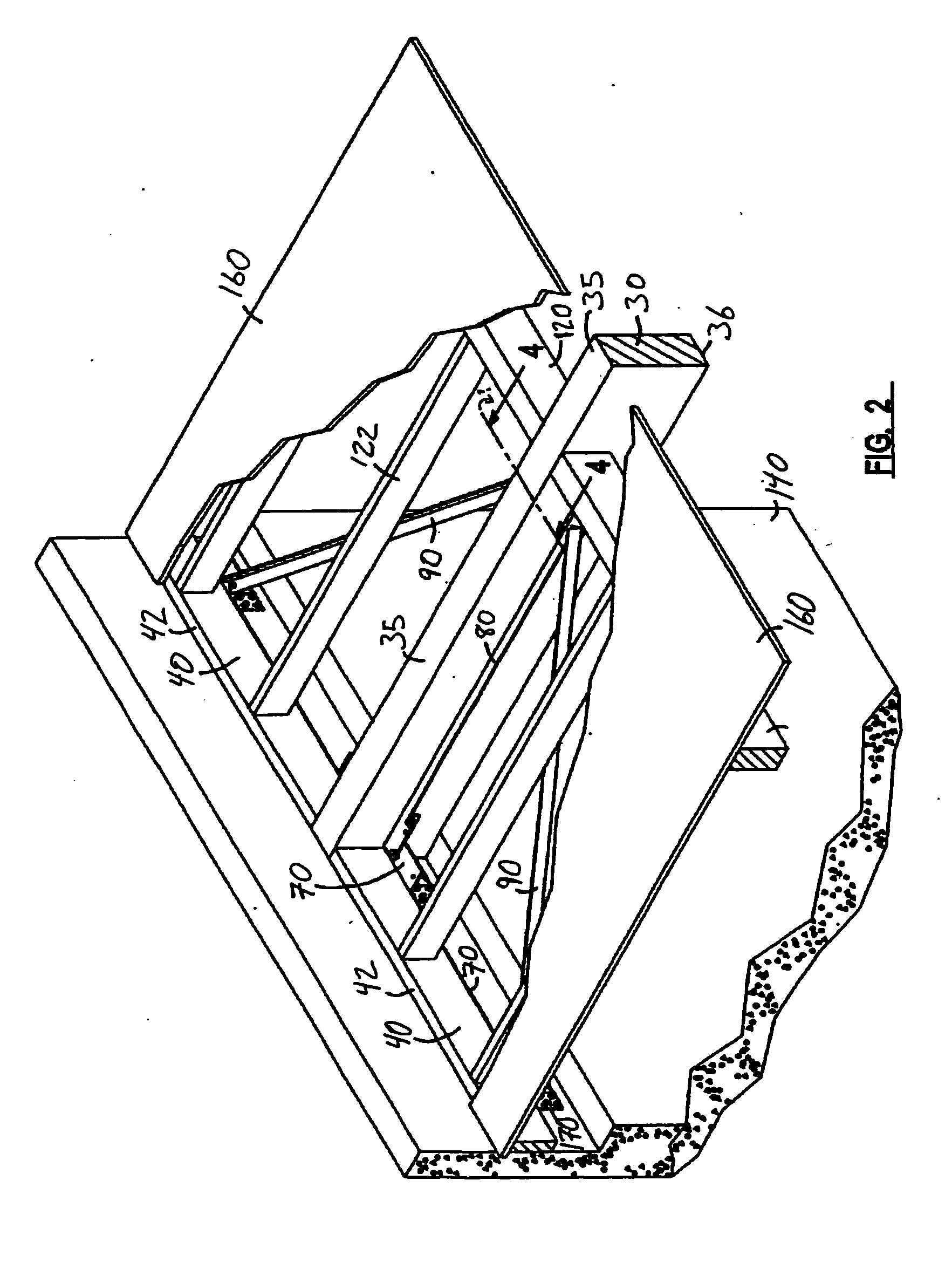
[0106]Referring to the drawings wherein like reference characters designate like or corresponding parts throughout the several views, and referring particularly to FIGS. 1-6, it is seen that a first embodiment illustrated in these drawings includes three elongated rigid (preferably metallic) bracket members 70, 80 and 90. These members may be used independently of each other, they may be used in combination with other support members, and / or they may be attached to each other in a triangular fashion as illustrated in FIG. 1. Some of the alternative and / or independent usages of members 70, 80 and 90 are described and illustrated in other embodiments herein.

[0107]In the exemplary triangular embodiments illustrated in FIGS. 1-6, and referring particularly to FIG. 3, it is seen that a first elongated member 70 is adapted for attachment along the underside 44 of a ledger 40 of a building roof, ceiling or floor support system. In some embodiments, bracket member 70 is not attached to ledg...


PUM


Abstract

The present invention includes a set of reinforcement and support devices for existing or new roof, ceiling and / or floor systems together with numerous variations that may be installed into existing buildings or new buildings to help prevent separation of wood or metal roof, ceiling and / or floor systems from the concrete, masonry or other types of walls supporting these systems in commercial, industrial and / or residential buildings. One embodiment includes a set of three brackets that are installed in a triangularly shaped arrangement along a side of a primary support beam and to the wall underneath a ledger, thus anchoring the support beam to the wall of the structure and stabilizing the roof, ceiling or floor it supports. Another embodiment includes a single integrated unit that attaches to the wall underneath the ledger and to an adjacent support board, thus anchoring the support board (and the system it supports) to the wall of the structure. Another embodiment includes an angle iron with predrilled holes that attaches through the ledger directly to the wall to reinforce the ledger and extend the area of horizontal support provided by the ledger. Other embodiments provide support structures that may be attached and arranged to provide specific structural support at designated locations, and / or to provide wall-to-wall structural support across the span of a roof, ceiling or floor. All embodiments may be adapted for use with ceilings, roofs or floors.

Description

BACKGROUND OF THE INVENTION[0001]1. Field of the Invention[0002]The present invention relates to reinforcing and supporting roof, ceiling or floor systems, and more particularly to methods and apparatus for providing improved support for new and existing roof, ceiling or flooring systems to help prevent failure in the event of seismic activity, wind, water, excessive weight buildup and the like.[0003]2. Description of the Prior Art[0004]Many types of buildings may be heavily damaged by seismic movement, high winds and other natural disasters. These include, but are not limited to, tilt-up buildings that have concrete walls which are formed and poured and cured flat on top of existing slabs on grade and then raised into position, masonry walls, pour-in-place concrete walls, or block walls. These varieties of walls anchor to roof systems constructed of wood usually with a series of primary beams (glued laminated beams—GLB's), secondary timber beams or purlins, joists spanning from pur...

Claims


Application Information

Patent Timeline
Patent Type & Authority Applications(United States)
IPC IPC(8): E04B9/06E04C3/02E04C3/30E04H9/14E04B1/19
CPCE04B5/12E04C3/02E04H9/028E04G23/0218E04H9/02E04C2003/026E04G23/0237E04G2023/0248E04H9/0237
Inventor DEANS, BRIAN W.DEANS, DUSTIN W.
Owner DEANS BRIAN W
Learn More