
Hydrokinetic coupling device, particularly for a motor vehicle

Active Publication Date: 2009-06-09
VALEO EMBRAYAGES SAS
View PDF13 Cites 2 Cited by
  • Summary
  • Abstract
  • Description
  • Claims
  • Application Information

AI Technical Summary

Benefits of technology

[0026]A main object of the invention is to provide a remedy for the disadvantages discussed above, and to provide a hydrokinetic coupling apparatus of the type defined earlier herein which will be reliable, simple and inexpensive, both in manufacture and in assembly.
[0030]Thanks to the invention, reliable joints are achieved, and the controlled performance of the friction welding operations enables high precision to be obtained during assembly of the turbine wheel, damper plate and turbine hub in a unitary sub-assembly.
[0031]In addition, friction welding is an advantageous manufacturing method which enables high precision, with high repeatability, to be obtained in mass production.
[0033]The weld bands of the welded joints have the advantage of being easily accessible, which facilitates the operations of control and / or cleaning, and it reduces the time which has hitherto been needed to carry out these operations.

Problems solved by technology

However, riveting is a method of making a joint which does not always give full satisfaction.
Riveting has various disadvantages, and in particular it requires costly machining operations by way of precision drilling in each of the components to be coupled together in rotation, to form the holes for the passage of the bodies of the rivets.
In addition, the heads of the rivets increase the general axial size of the apparatus, and although riveting is simple to apply, it is an expensive way of fastening because of the overall time needed to carry out all the various operations.
Rigid couplings of the meshed type also have disadvantages, in particular as regards treatments and precision machining operations in order to make the complementary male and female parts, and they are therefore expensive.
In addition, a coupling of this kind is not reliable enough in respect of its liability to wear, so that undesirable noise will tend to occur.
Nevertheless, in currently known apparatus designs, the turbine wheel, turbine hub and damper plate do not enable operations of these kinds to be easily performed, and therefore do not give any guarantee as to the quality and reliability of the welded joints.
In addition, in current motor vehicles, the space available for fitting the engine is becoming smaller and smaller, especially because of the addition of further components, so that smaller size, and consequently a high degree of axial compactness, of the apparatuses, is constantly being sought.
Now, those designs which are currently known do not enable access to be gained satisfactorily to the weld bands of the first and second joints, and particularly to the inner rear weld band of the second joint.

Method used


Image

  • Hydrokinetic coupling device, particularly for a motor vehicle
  • Hydrokinetic coupling device, particularly for a motor vehicle

Examples


Embodiment Construction

[0045]In the following description, those components which are identical, similar or analogous to each other will be designated by the same reference signs.

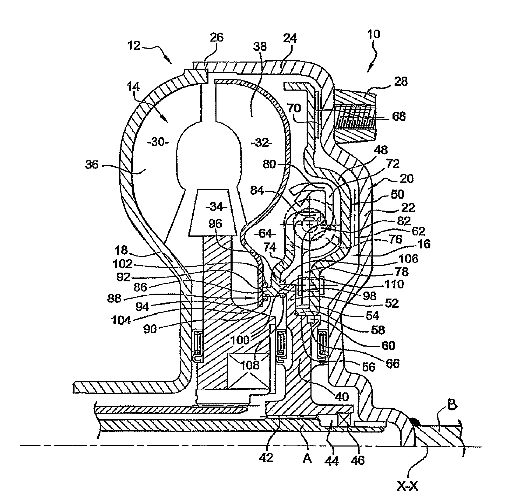
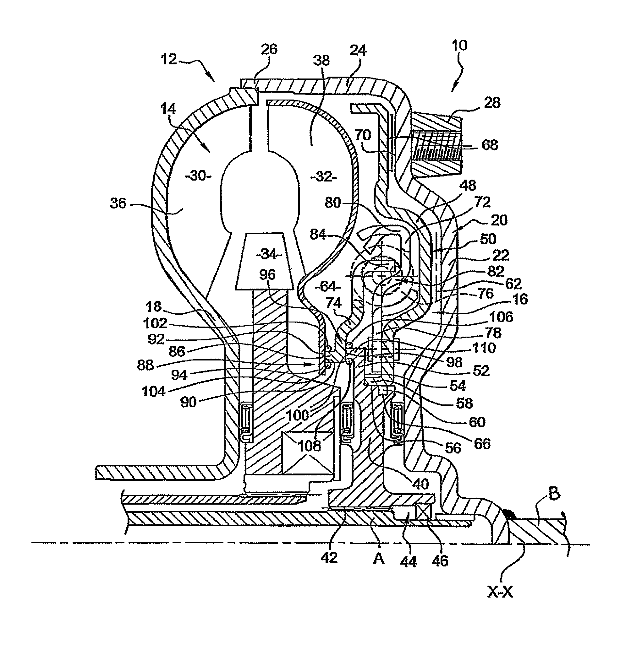
[0046]In order to facilitate understanding of the description and claims, we will use, though without limitation, “front” and “rear” orientations which correspond to the left and right hand sides respectively in the drawing; and “axial—radial” and “external / outer / outside—internal / inner / inside” orientations with respect to the general axis of rotation X-X of the hydrokinetic coupling apparatus.

[0047]The drawing shows a hydrokinetic coupling apparatus 10 which in this case is of the “monoface” type and which comprises a torque converter 14 and a lock-up clutch 16, which are arranged within a sealed casing 12 filled with oil.

[0048]The function of a hydrokinetic coupling apparatus 10 of this kind is to couple together two shafts, namely a driving shaft B and a driven shaft A respectively in the case of an application to an automatic ...


PUM

PropertyMeasurementUnit
Diameteraaaaaaaaaa

Abstract

The invention relates to a hydrokinetic coupling device (10) characterized by the fact that the web (74) comprises, at the inner radial end thereof, a collar (86), which axially extends toward the front between the turbine wheel (32) and the turbine hub (40) and which is rotationally joined by friction welding respectively: at the front, to the turbine wheel (32) by a first weld joint (88) provided between a front annular contact face (90) of the collar (86) and a rear welding face (92) opposite the inner radial periphery of the turbine wheel (32) and; at the rear, to the turbine hub (40) by a second rear weld joint (96) provided between a rear annular contact face (98) of the collar (86) and a front welding face (100) opposite the outer radial periphery of the turbine hub (40).

Description

[0001]INTERNATIONAL PATENT APPLICATION NO. PCT / FR2005 / 050130, PUBLICATION NO. WO2005 / 085678BACKGROUND OF THE INVENTION[0002]1. Field of the Invention[0003]The present invention relates to hydrokinetic coupling apparatus, especially for a motor vehicle.[0004]2. Description of the Related Art[0005]Numerous hydrokinetic coupling apparatuses are known in the current state of the art, among which are various designs of apparatus according to their applications, and in particular apparatus of the “monoface”, “biface” or again “multi-disc” types.[0006]It is for example known, from the documents FR-A-2 825 770 or FR-A-2 765 938, to provide a hydrokinetic coupling apparatus of the “monoface” type, which comprises, considered axially from front to rear:[0007]a casing consisting of a rear shell which is adapted to be coupled in rotation to a driving shaft, an impulse wheel, and a front shell;[0008]a turbine wheel, which is arranged for rotation with a turbine hub, which is adapted to be couple...

Claims


Application Information

Patent Timeline
IPC IPC(8): F16H45/02B23K20/12F16H41/24F16H41/28
CPCB23K20/12F16H41/28F16H45/02F16H2045/0294
Inventor ARHAB, RABAHTERMENON, NORBERTO
Owner VALEO EMBRAYAGES SAS
Learn More