Manipulator and robot

a robot and manipulator technology, applied in the field of manipulators and robots, can solve the problems of increasing the weight of the actuator, complicated control of the plurality of actuators, complicated mechanism, etc., and achieve the effect of simplifying the mechanism and control algorithm, and ensuring the grip of objects

Inactive Publication Date: 2009-01-29
KK TOSHIBA
View PDF9 Cites 42 Cited by
  • Summary
  • Abstract
  • Description
  • Claims
  • Application Information

AI Technical Summary

Benefits of technology

[0009]An object of the present invention is to provide a manipulator and a robot, which can reliably grip objects of various shapes with a simplified mechanism and control algorithm.

Problems solved by technology

However, in this mechanism, since a plurality of actuators are used, the mechanism is complicated, and moreover, the weight thereof is also increased.
Furthermore, it is complicated to control the plurality of actuators.
However, in this mechanism, the respective joints interlock with one another in a completely fixed relationship, and the fingers cannot achieve a posture that goes along a surface shape of the object.
However, in this mechanism, the clutches are arranged in the respective joints, whereby the mechanism becomes complicated, and the weight thereof is also increased.
Moreover, the conventional gripper in which the number of actuators has been decreased as much as possible has been incapable of dealing with a variety of shapes of recessed-shaped object such as a bowl, a rod-shaped object such as a chopstick, and the like.

Method used


Image

  • Manipulator and robot
  • Manipulator and robot
  • Manipulator and robot

Examples


first embodiment

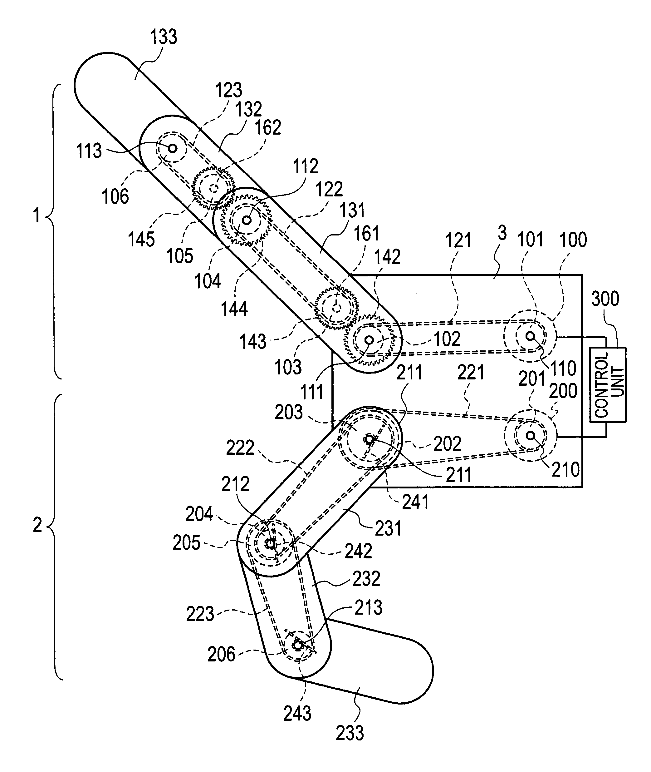
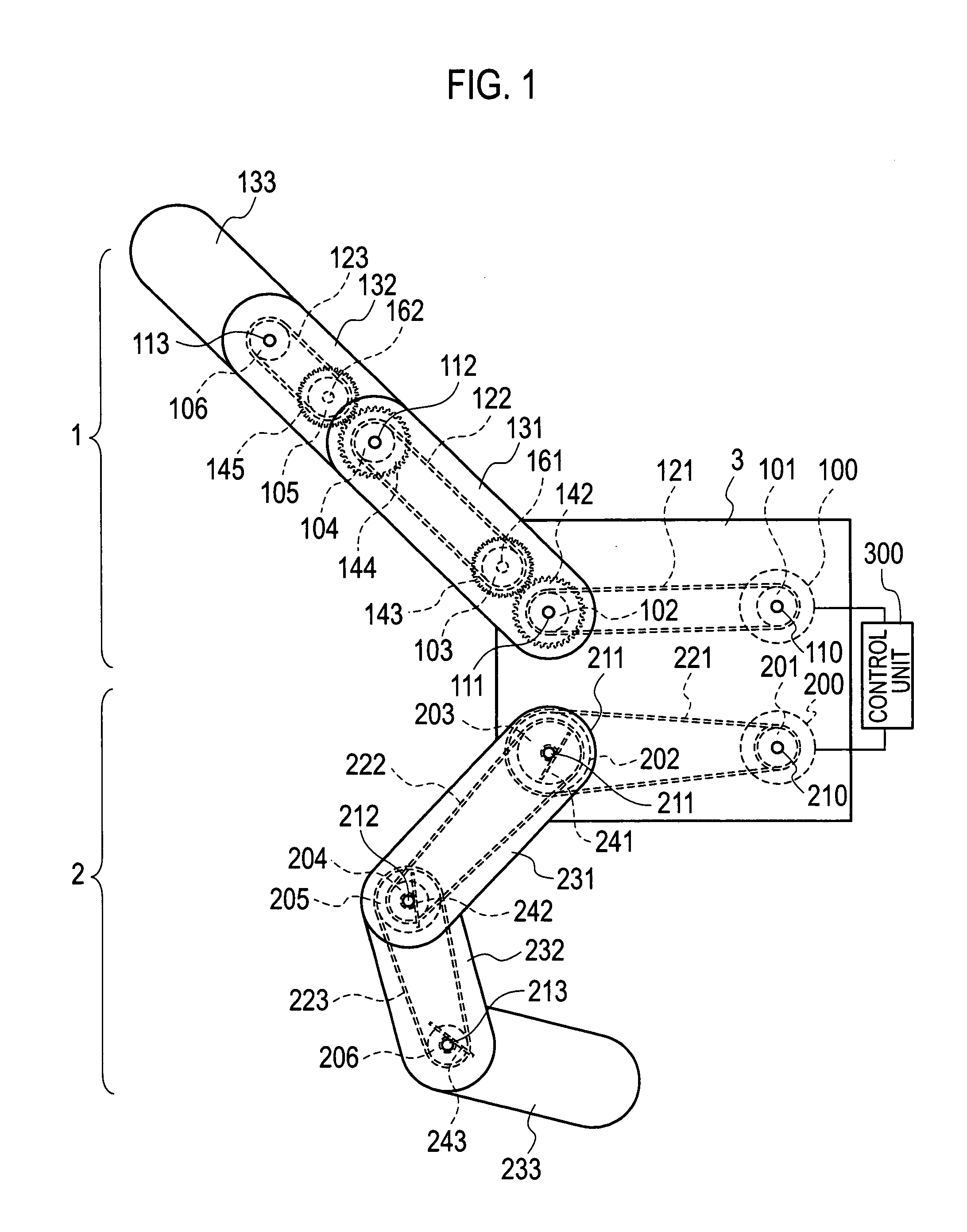
[0033]As shown in FIG. 1, a manipulator according to a first embodiment of the present invention is a gripper including: a first finger 1 that has a sequence of links 131, 132 and 133 and a plurality of joint shafts 111, 112 and 113, in which the sequence of links 131, 132 and 133 move (bend) so as to close the first finger 1 in an interlocking manner with one another so that rotation angles of the plurality of joint shafts 111, 112 and 113 can maintain a fixed relationship. The gripper also includes a second finger 2 that is disposed opposite the first finger 1. The second finger 2 also has a plurality of joint shafts 211, 212 and 213 and a sequence of links 231, 232 and 233, in which the sequence of links 231, 232 and 233 move (bend) so as to close the second finger 2 sequentially from the link 231 assigned at a basal side of the second finger 2 thereof, and when the link 231 assigned at the basal side contacts an object, the link 232 adjacent to the link 231 moves in the closing ...

second embodiment

[0069]In a second embodiment of the present invention, a description will be made of grippers having soft members are arranged thereon. In order to positively grip an object, the contact area between the object and the grippers is desirably increased as much as possible. However, the contact area cannot be increased sufficiently by only using the links. Accordingly, soft members 41, 42, 43, 44, 45 and 46 are arranged on surfaces of the first finger 1 and the second finger 2. A soft member 40 is also disposed on a surface of the first portion 3 between the first finger 1 and the second finger 2.

[0070]In the first finger 1, as shown in FIG. 23, two side plate members (third links) 133 are joined to a center member 14 by screws and the like (not shown).

[0071]In accordance with the second embodiment of the present invention, the soft members 41, 42, 43, 44, 45 and 46 are arranged on the surfaces of the first finger 1 and the second finger 2, thus making it possible to further increase t...

third embodiment

[0074]In a third embodiment of the present invention, a description will be made of a gripper having a plurality of fingers. As shown in FIG. 24, the gripper according to the third embodiment of the present invention includes a plurality of second fingers 2, 2a, 2b and 2c.

[0075]The plurality of second fingers 2, 2a, 2b and 2c are driven by the one drive source 200. Drive power is transmitted from the drive source 200 through the timing belt 221 to a second joint shaft (coupling shaft) 211. The power is transmitted from the joint shaft 211 to fingertips of the plurality of second fingers 2, 2a, 2b and 2c through pulleys 202, 203a, 203b and 203c of the plurality of second fingers 2, 2a, 2b and 2c and through timing belts 222, 222a, 222b and 222c of the plurality of second fingers 2, 2a, 2b and 2c.

[0076]As shown in FIG. 25, an object 15 having a three-dimensional shape can be gripped by using the first finger 1 and the plurality of second fingers 2, 2a, 2b and 2c. Here, if rigidity o...


PUM


Abstract

A manipulator includes: a first finger having a sequence of first links and first joint shafts, the sequence of first links bending so that rotation angles of the first joint shafts maintain a fixed relationship; a second finger having a sequence of second links bending sequentially from one of the second links assigned at a basal side of the second finger; and drive sources driving the first and second fingers, wherein an adjacent second link next to the second link assigned at the basal side moves after contacting the second link assigned at the basal side with the object.

Description

CROSS REFERENCE TO RELATED APPLICATIONS AND INCORPORATED BY REFERENCE[0001]The application is based upon and claims the benefit of priority from the prior Japanese Patent Applications No. P2007-196327, filed on Jul. 27, 2007; the entire contents of which are incorporated herein by reference.BACKGROUND OF THE INVENTION[0002]1. Field of the Invention[0003]The present invention relates to a manipulator and a robot for gripping an object.[0004]2. Description of the Related Art[0005]Heretofore, a large number of robot arms and grippers, which perform only a routine task and grip only an object with a definite shape, have been developed. However, in recent years, a service robot provided with arms, which operates at a person's side and assists a person in his / her daily life, has been in a development process. The robot, as described above, must perform not only routine tasks but also tasks corresponding to a variety of situations. Moreover, objects to be handled by the robot have indefini...

Claims


Application Information

Patent Timeline
Patent Type & Authority Applications(United States)
IPC IPC(8): B25J15/08
CPCB25J9/104B25J9/1612Y10T74/20305B25J19/023B25J15/0009
Inventor NAKAMOTO, HIDEICHI
Owner KK TOSHIBA
Why Eureka
Try Eureka