Thermoelectric means and fabric-type structure incorporating such a means

a fabric-type structure and thermoelectric means technology, applied in the direction of thermoelectric devices with peltier/seeback effect, thermoelectric device junction materials, electrical apparatus, etc., can solve the problems of not being completely self-sufficient, limiting the type of materials that can be used, and not being able to exploit all the heat emitted by the human body, so as to achieve the effect of easy optimization of the thermoelectric performance of the structur

Inactive Publication Date: 2009-01-29
COMMISSARIAT A LENERGIE ATOMIQUE ET AUX ENERGIES ALTERNATIVES
View PDF5 Cites 44 Cited by
  • Summary
  • Abstract
  • Description
  • Claims
  • Application Information

AI Technical Summary

Benefits of technology

[0027]The invention is based on the use of thermoelectric means which, before their assembly into the structure, exhibit a thermoelectric functionality. This enables the thermoelectric performance of the structure to be easily optimized according to the characteristics required by the electronic means, which need a power supply.

Problems solved by technology

The main drawback of these textiles is therefore that they are not completely self-sufficient.
The use of weaving or knitting limits the type of materials that can be used, these having to be in the form of wires and to be sufficiently flexible.
They therefore fail to exploit all the heat emitted by the human body when the structure is used to produce a garment.
Moreover, the use of wires made of metallic materials or alloys necessarily limits the thermoelectric performance of the structure obtained, these materials themselves being of low performance.
In any case, the optimization of the thermoelectric performance of the structure is limited by the characteristics of the weaving looms or knitting machines, these imposing the diameter of the wires, the thickness of the structure and also the spacing of the wires or the size of the mesh cells.
It therefore does not have the characteristics of a fabric and in particular cannot be used directly to produce a garment.

Method used


Image

  • Thermoelectric means and fabric-type structure incorporating such a means
  • Thermoelectric means and fabric-type structure incorporating such a means
  • Thermoelectric means and fabric-type structure incorporating such a means

Examples


Embodiment Construction

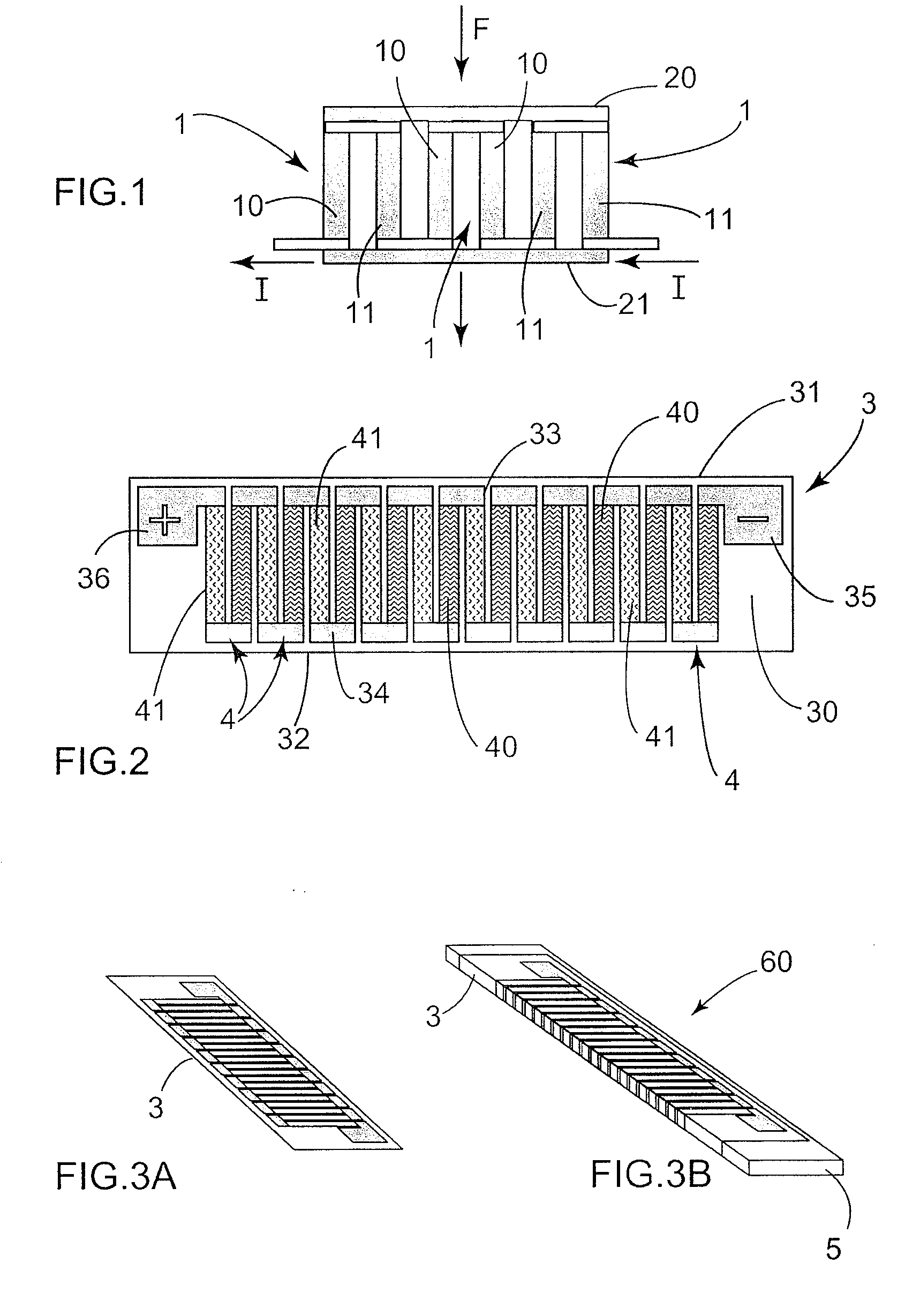
[0046]Referring firstly to FIG. 1, this illustrates a thermoelectric converter consisting here of three pairs 1 of electrically connected conductors. Each pair comprises two electrical conductors 10, 11 of different nature.

[0047]As illustrated in FIG. 1, the two conductors 10, 11 of a given pair 1 are electrically connected in series, the pairs 1 also being electrically connected in series. The current flowing within the converter is indicated schematically by I.

[0048]Finally, the pairs of conductors are thermally connected in parallel. In the example illustrated in FIG. 1, a temperature difference exists between the hot face 20 and the cold face 21 of the thermoelectric converter, through which a heat flux illustrated by the arrow F flows.

[0049]The efficiency of such a converter is directly proportional to the temperature difference applied between the two faces of the converter.

[0050]Referring now to FIG. 2, this illustrates the first step in the manufacture of a thermoelectric me...


PUM


Abstract

The invention relates to a thermoelectric means (60) that can be woven or knitted, taking the form of an elongate body and having on its surface at least one converter for converting thermal energy into electrical energy. The invention also relates to a structure for converting a temperature difference over the thickness of the structure into electricity, which consists of an assembly formed by the interlacement of textile fibers (8), of said thermoelectric means (60) and of connection means (7).

Description

CROSS REFERENCE TO RELATED APPLICATIONS[0001]This application claims priority from French patent application No. 0705331, filed Jul. 23, 2007.FIELD AND BACKGROUND OF THE INVENTION[0002]The invention relates to the field of energy recovery systems applied to fabrics.[0003]It relates to a structure of the fabric type for converting a temperature difference into electricity.[0004]Textiles into which functions associated with electronic means are incorporated exist at the present time. These functions consist of the collection of information about the environment, thanks to sensors, such as temperature, atmospheric pressure or humidity sensors, or else detectors, or of the measurement of physiological parameters (such as heart beat, body temperature or blood pressure).[0005]At the present time, these textiles incorporating electronic functions use, as energy source, lithium storage batteries which therefore have to be provided in the assembly incorporating this type of textile.[0006]The...

Claims


Application Information

Patent Timeline
Patent Type & Authority Applications(United States)
IPC IPC(8): H01L35/16H01L35/28H01L35/14
CPCH01L35/32H10N10/17
Inventor PLISSONNIER, MARCBRETON, YANNICKCHARTIER, ISABELLELANIER, THIERRYNAVONE, CHRISTELLE
Owner COMMISSARIAT A LENERGIE ATOMIQUE ET AUX ENERGIES ALTERNATIVES
Why Eureka
Try Eureka