Method, arrangement and valve for controlling rock drilling

a technology for controlling valves and rock drilling, applied in the direction of functional valve types, servomotors, manufacturing tools, etc., can solve the problems of increasing the risk of drill bit sticking, the function and reliability also change, and achieve the effect of slowing down the spool movement and improving the implementation. and functionally better

Inactive Publication Date: 2009-01-29
SANDVIK MINING & CONSTR OY
View PDF21 Cites 34 Cited by
  • Summary
  • Abstract
  • Description
  • Claims
  • Application Information

AI Technical Summary

Benefits of technology

[0004]It is an object of the present invention to provide a method, arrangement and valve, by which the adjustment may be implemented more reliably and functionally better. The method of the invention is characterized by using the pressure difference acting across the rotation motor to control a separate feed regulating valve, which is arranged to control the feed control valve by means of separate control pressure conduits leading to control pressure surfaces of the spool of the feed control valve in such a manner that as said pressure difference increases but remains below said threshold value, the feed regulating valve regulates pressure values of control pressures controlling the feed control valve according to said pressure difference so that the feed control valve, affected by these control pressures, reduces the flow rate of the hydraulic fluid to be supplied to the feed motor correspondingly. The arrangement of the invention is characterized in that the feed control valve is a flow regulating valve controlled by a pressure difference, that the pressure difference acting across the rotation motor in the hydraulic fluid conduits of the rotation motor is connected to control the feed control valve in such a manner that as the pressure difference increases, the feed control valve reduces the flow of the hydraulic fluid to the feed motor and after the pressure difference exceeds a predetermined threshold value, it switches the hydraulic fluid flow to the feed motor to the opposite direction so that the feed motor is switched to a return motion. The valve of the invention is characterized in that the valve comprises a retarding element, which allows the spool to move freely when the spool is moving in one direction, but slows down the spool movement when the spool tends to move in the opposite direction.

Problems solved by technology

The starting point in the use of pressure acting on the rotation motor is that as the rotation resistance increases, the risk that the drill bit gets stuck increases.
A problem with the known solutions is that as the drilling conditions and hydraulic fluid properties vary, the function and its reliability also change considerably.

Method used


Image

  • Method, arrangement and valve for controlling rock drilling
  • Method, arrangement and valve for controlling rock drilling

Examples


Embodiment Construction

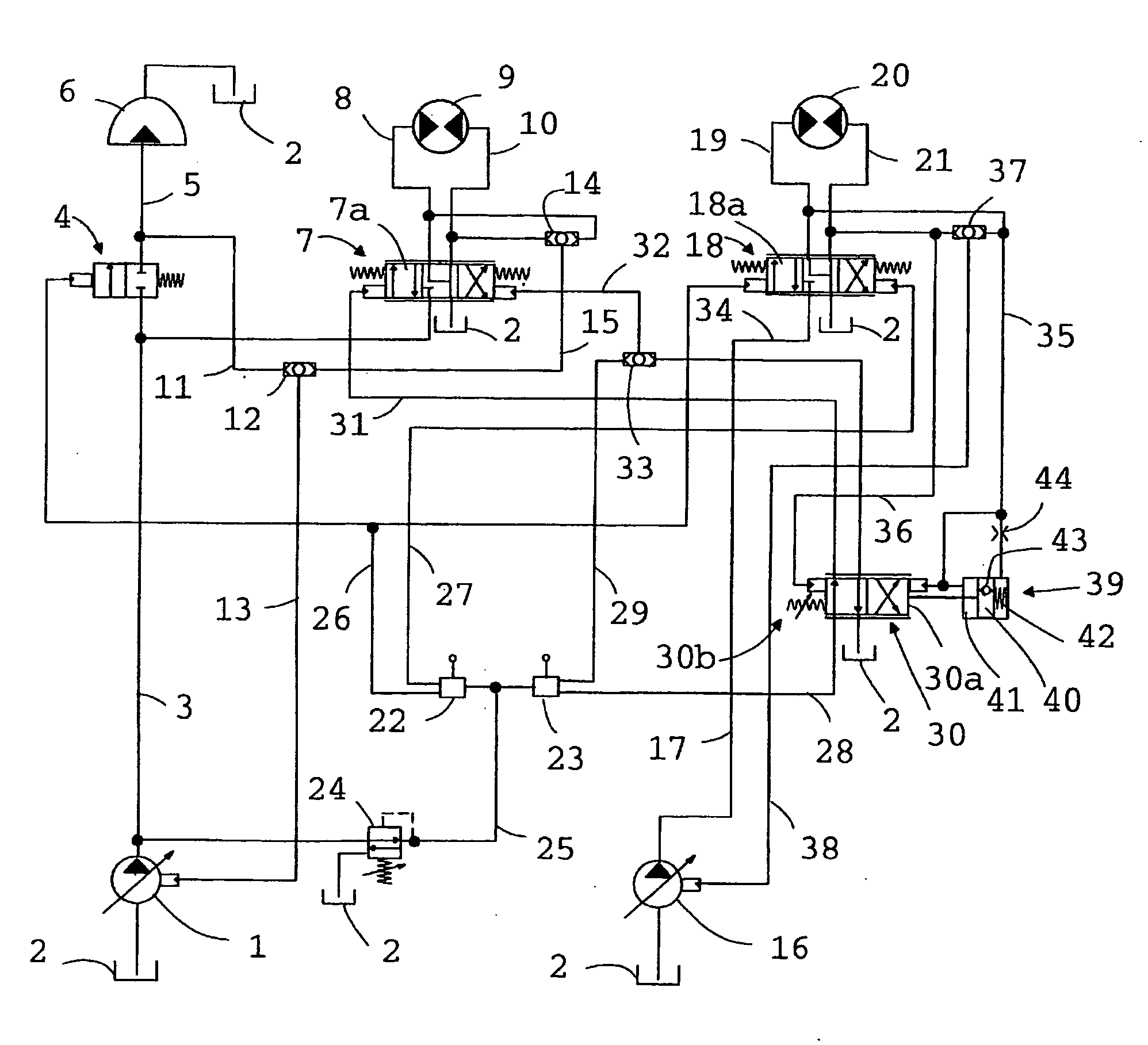
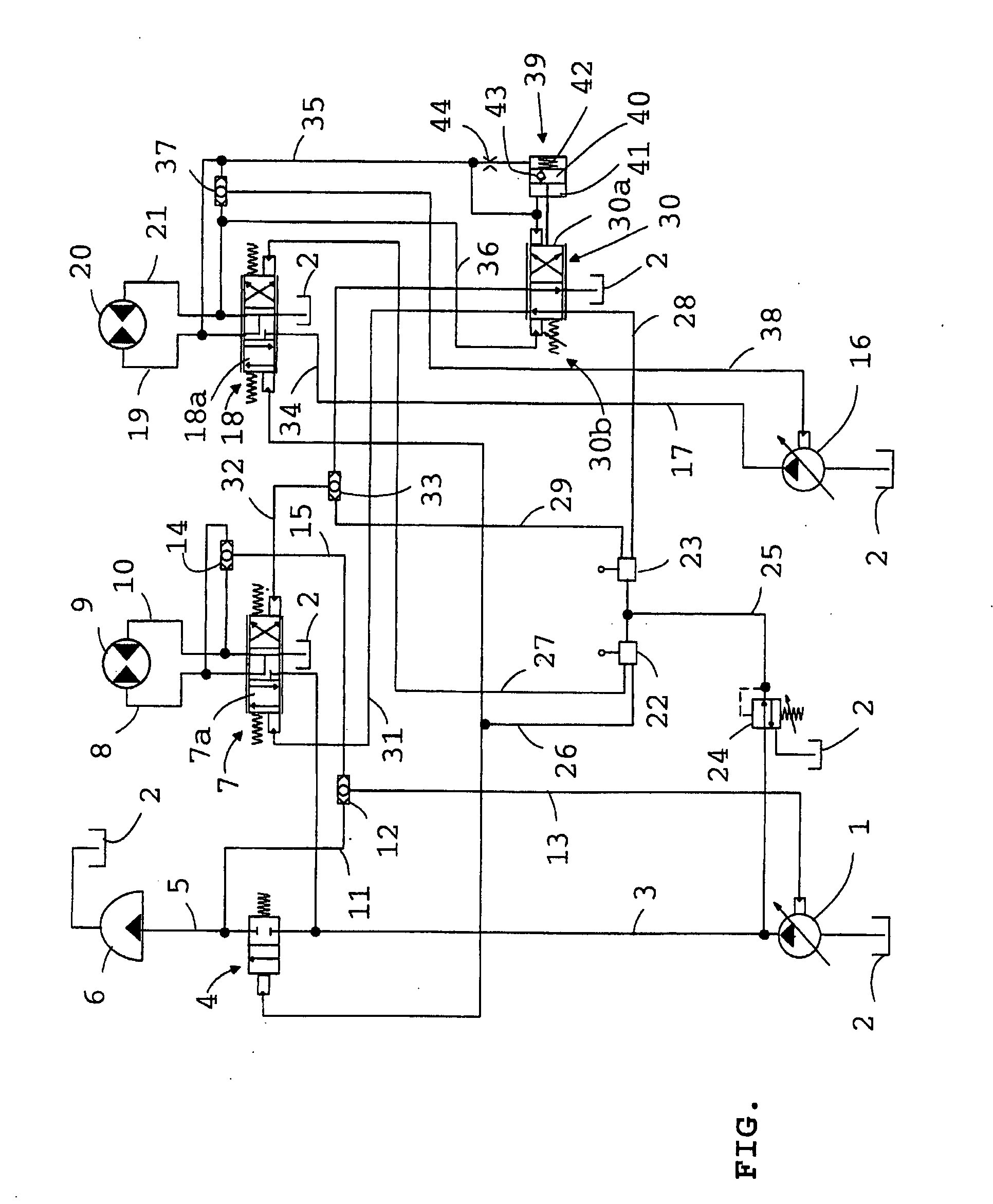
[0008]The drawing shows an embodiment of the invention schematically as a hydraulic diagram. It comprises a first hydraulic fluid pump 1, which is a pressure-controlled volume flow pump. The pump 1, which supplies hydraulic fluid to both a percussion apparatus and a feed motor, sucks hydraulic fluid from a hydraulic fluid container 2. From the pump 1, the hydraulic fluid flows along a conduit 3 to a percussion control valve 4 and, during percussion, further via a hydraulic fluid conduit 5 to a percussion apparatus 6. From the percussion apparatus 6, the hydraulic fluid flows back to the hydraulic fluid container 2. The hydraulic fluid flows further from the pump 1 via the conduit 3 to a feed control valve 7, from which it flows via a conduit 8 to a feed motor 9 of feed equipment, further via a conduit 10 back to the feed control valve 7 and through it to the hydraulic fluid container 2. The feed motor may be either a hydraulically operated motor known per se or a hydraulic cylinder ...


PUM


Abstract

A method, arrangement and valve for controlling rock drilling. In the method, a pressure difference acting across a rotation motor is used to regulate a separate feed regulating valve, which, on the basis of this, regulates control pressures of a feed control valve. The arrangement comprises a separate feed regulating valve, which, under the influence of the pressure difference acting across the rotation motor, regulates control pressures of a feed control valve. The valve comprises a separate retarding element, which slows down the returning of a spool of the valve to the normal position, if the spool has moved away from its normal position under the influence of the pressure difference acting across the rotation motor.

Description

BACKGROUND OF THE INVENTION[0001]The invention relates to a method for controlling rock drilling, the method comprising controlling the feeding of a rock drilling machine by means of a pressure difference acting across the rotation motor of a drill rod in such a manner that as rotation resistance increases, after the pressure difference caused by it and acting on the rotation motor exceeds a predetermined threshold value, it brings the spool of a feed control valve controlling the feeding of hydraulic fluid supplied to a feed motor to a position, in which the feed motion is switched to a return motion. The invention also relates to an arrangement for controlling rock drilling, the arrangement comprising a rock drilling machine provided with a percussion apparatus and a rotation motor and a feed motor for pushing the rock drilling machine and a drill rod connected thereto towards material to be drilled and for returning it back, a feed control valve for regulating the feeding of hydr...

Claims


Application Information

Patent Timeline
Patent Type & Authority Applications(United States)
IPC IPC(8): E21B44/06E21BF15B11/16
CPCE21B44/06F15B2211/7058F15B2211/20546F15B2211/20576F15B2211/251F15B2211/30525F15B2211/3127F15B2211/3144F15B2211/31576F15B2211/329F15B2211/50554F15B2211/50572F15B2211/6054F15B2211/6057F15B11/165Y10T137/7837Y10T137/86574F15B11/16
Inventor PELTONEN, VESA
Owner SANDVIK MINING & CONSTR OY
Why Eureka
Try Eureka