Double-action fluid weighing and dispensing process and system

Active Publication Date: 2009-01-29
GCP APPL TECH INC
View PDF19 Cites 24 Cited by
  • Summary
  • Abstract
  • Description
  • Claims
  • Application Information

AI Technical Summary

Benefits of technology

[0007]In surmounting the disadvantages of prior art volumetric fluid dispensing systems, the present invention employs an air-operated dispensing pump a

Problems solved by technology

Mechanical fluid meters are often problematic due to their moving parts and due to the effects of chemical attack on the numerous parts.
The weight sensing system of

Method used


Image

  • Double-action fluid weighing and dispensing process and system
  • Double-action fluid weighing and dispensing process and system

Examples


Embodiment Construction

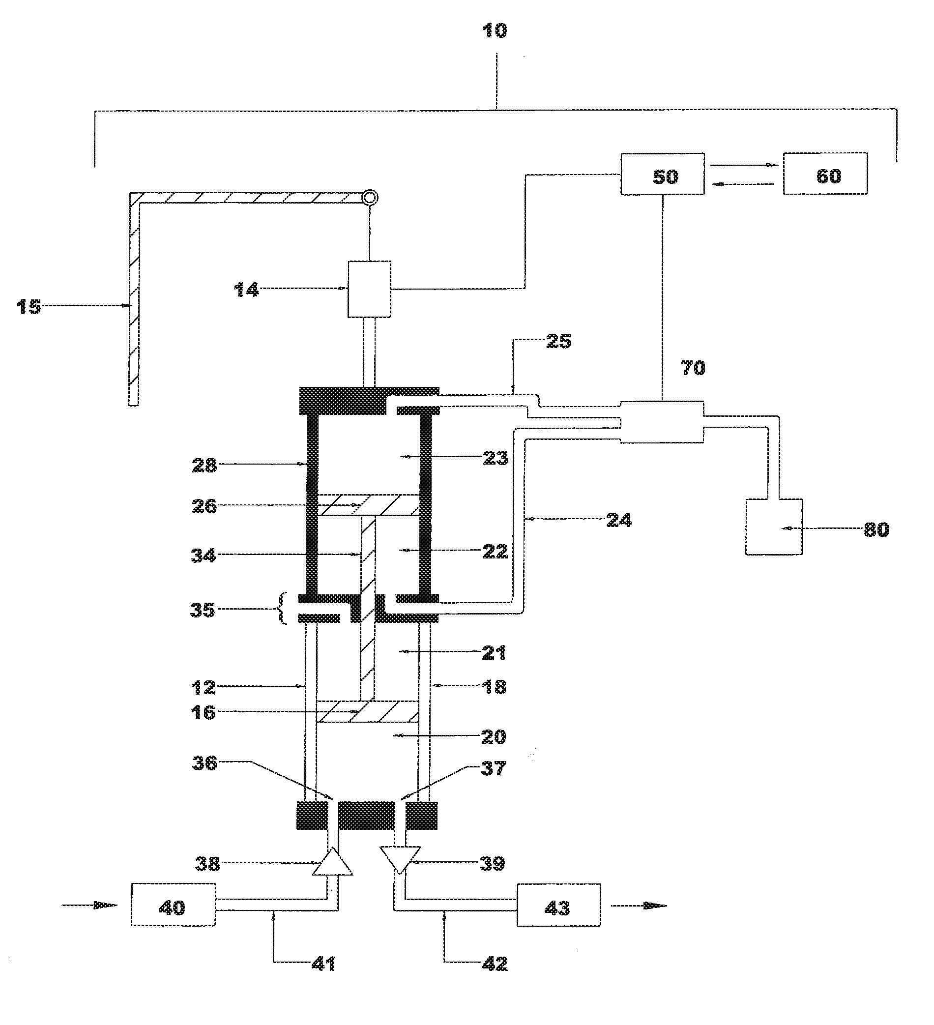
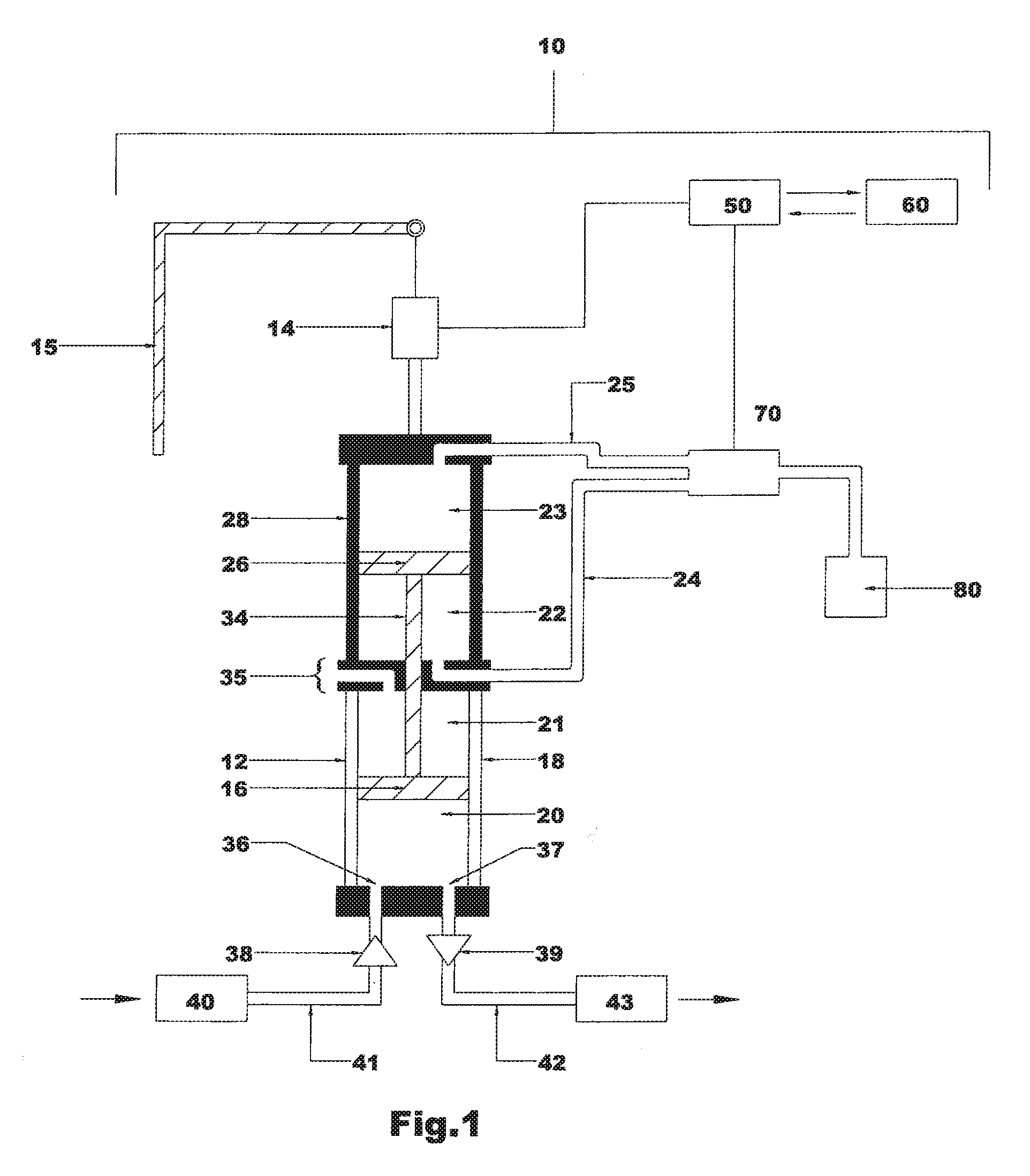
[0020]As shown in FIG. 1, an exemplary fluid-dispensing apparatus 10 and process of the present invention comprises an air-operated pump 12 having at least one piston 16 that is slidably housed within a piston sleeve housing 18, a fluid chamber 20 defined within the piston sleeve housing 18 for admitting and expelling a fluid (as designated at 40), and a load cell 14 for supporting and measuring substantially at least 100% of the weight of the pump 12 and fluid contained within the fluid chamber 20 of the pump 12. Flexible tubing (as designated at 24, 25, 41, and 42) connects the pump 12 components (as designated at 40, 50, 70, and 43 and described hereinafter) whose weights are preferably not supported by the load cell 14.

[0021]The piston sleeve housing material, including the sleeve walls, end caps or barriers, may comprise known materials depending on the nature of the fluids 40 or chemicals to be dispensed. Such materials may include those typically used for fluid pumps, such as...


PUM


Abstract

Apparatus and process for dispensing fluids, such as chemical concrete admixtures, using an air-operated pump and load cell for supporting and measuring at least substantially 100% of the weight of the pump and fluid dispensed through the pump. A double-action, dual piston design of the air-operated pump allows positive air pressure to be used during both fluid-filling and fluid-expelling phases.

Description

FIELD OF THE INVENTION[0001]The present invention relates to dispensing of fluids, and more particularly to a novel apparatus and process for weight-based dispensing of fluid concrete admixtures, as well as other fluids.BACKGROUND OF THE INVENTION[0002]Equipment for dispensing chemical additives and admixtures into concrete is conventionally based on volumetric measurement. Such equipment includes mechanical fluid meters, sight bottles as visual indicators, control elements, bladder tanks, tubing, valves and pumps. Volumetric systems require consideration of the viscosity of the various fluids to be dispensed, and the viscosity can vary considerably depending on temperature and other factors.[0003]Mechanical fluid meters are often problematic due to their moving parts and due to the effects of chemical attack on the numerous parts. Sight bottles are typically constructed out of steel or acrylic, and are calibrated. The sight bottles need to be located at or near the concrete batchin...

Claims


Application Information

Patent Timeline
IPC IPC(8): G01F11/00G01G13/00B65D88/54
CPCF04B9/125F04B13/00G01F11/04F04B2205/09F04B49/06
Inventor RAMNARINE, REYNOLD
Owner GCP APPL TECH INC
Why Eureka
Try Eureka