
Systems and methods for antenna calibration

a technology of collision avoidance system and directional antenna, which is applied in the direction of antennas, instruments, measurement devices, etc., can solve the problems of inability to correct for phasing errors, distorted directional or omnidirectional beam patterns emanating from the antenna, and added cost and volume to the tcas system

Active Publication Date: 2009-01-29
L3 TECH INC
View PDF36 Cites 43 Cited by
  • Summary
  • Abstract
  • Description
  • Claims
  • Application Information

AI Technical Summary

Benefits of technology

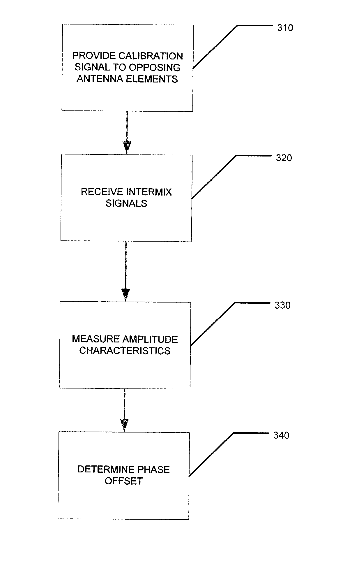
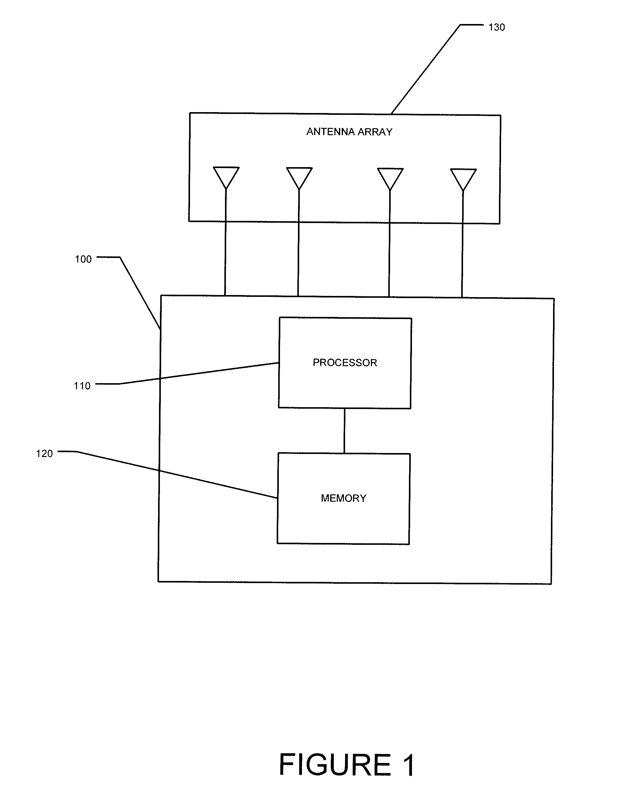
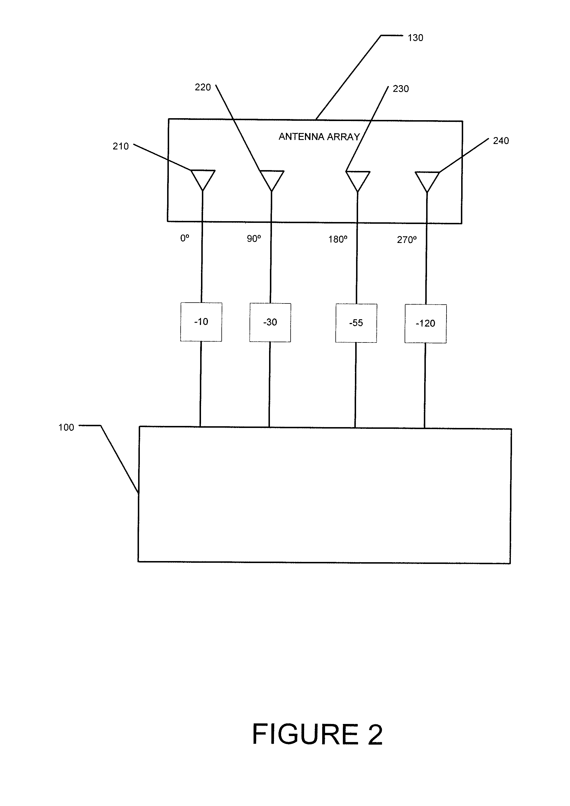
The present invention relates to systems and methods for calibrating antennas, particularly directional TCAS antennas, without the need for phase detector devices. The method involves simultaneously providing a calibration signal to two elements of the antenna and measuring the amplitude characteristic of an intermix signal received by a third element of the antenna. The phase offset can then be determined and used to adjust the signals transmitted from the first and second elements of the antenna. This allows for accurate synchronization of signals between the different elements of the antenna. The invention can be implemented using a processor, antenna, and memory, and can be used with any directional TCAS antenna.

Problems solved by technology

If the phase of the signal provided to the antenna elements is not properly calibrated to account for such phase offsets, the directional or omnidirectional beam patterns emanating from the antenna may be distorted.
This can result in added cost and volume to TCAS systems, and still may not be able to correct for phasing errors resulting from the design or construction of the antenna itself.

Method used


Image

  • Systems and methods for antenna calibration
  • Systems and methods for antenna calibration
  • Systems and methods for antenna calibration

Examples


Embodiment Construction

[0002]1. Field of the Invention

[0003]The present invention relates to systems and methods for antenna calibration, and more particularly, to systems and methods for calibrating a Traffic Alert Collision Avoidance System (TCAS) directional antenna.

[0004]2. Background of the Invention

[0005]TCAS systems are currently used to help avoid collisions between aircraft. TCAS equipment aboard a monitoring aircraft periodically transmits interrogation signals that are received by transponders on other target aircraft. In response to an interrogation signal, a target aircraft's transponder transmits a reply signal. The TCAS equipment aboard the monitoring aircraft can then use information contained in the reply signal, as well as information determined from the signal (such as the bearing to the target aircraft determined from the signal) to identify potential collisions. The detailed operation of TCAS is further discussed in: Radio Technical Commission for Aeronautics (RTCA) DO-185A, “Minimum ...


PUM


Abstract

A method according to an aspect of the present invention includes determining a phase offset by simultaneously providing a calibration signal to a first element of an antenna and a second element of the antenna opposite the first element. The method further includes receiving an intermix signal by a third element of the antenna, measuring an amplitude characteristic for the intermix signal, and determining a phase offset based on the amplitude characteristic. The phase offset can be used to adjust a signal provided to the first element so that it is in phase with the signal provided to the second element. This method can account for phase errors due to the construction or design of the antenna, and allows antenna elements to be calibrated without the need for phase detector devices.

Description

CROSS-REFERENCE TO RELATED APPLICATION[0001]This application claims priority to U.S. Provisional Patent Application Ser. No. 60 / 951,402 filed Jul. 23, 2007, the disclosure of which is incorporated herein by reference in its entirety.DESCRIPTION OF THE INVENTION[0002]1. Field of the Invention[0003]The present invention relates to systems and methods for antenna calibration, and more particularly, to systems and methods for calibrating a Traffic Alert Collision Avoidance System (TCAS) directional antenna.[0004]2. Background of the Invention[0005]TCAS systems are currently used to help avoid collisions between aircraft. TCAS equipment aboard a monitoring aircraft periodically transmits interrogation signals that are received by transponders on other target aircraft. In response to an interrogation signal, a target aircraft's transponder transmits a reply signal. The TCAS equipment aboard the monitoring aircraft can then use information contained in the reply signal, as well as informat...

Claims


Application Information

Patent Timeline
Patent Type & Authority Applications(United States)
IPC IPC(8): G01S7/40G01S13/933
CPCH01Q3/267G01S7/4017G01S7/4026G01S13/781G01S13/933
Inventor STAYTON, GREGORY T.
Owner L3 TECH INC
Learn More