Image projection method and projector
Active Publication Date: 2009-01-29
SHARP KK
1 Cites 21 Cited by
AI-Extracted Technical Summary
Problems solved by technology
However in many cases, the projector cannot be arranged ...
Abstract
An image projection method and a projector are provided to be able to change aspect ratio or resolution of a projection image, without setting of keystone correction again. The projector sets a displayable region with a shape according to an aspect ratio and a resolution of the projection image. The projector converts coordinates of the displayable region into coordinates in a screen coordinate system, and generates a rectangular area with a desired aspect ratio in a region corresponding to the displayable region in the screen coordinate system and a portion included in a projecting range. The projector converts the coordinates of a rectangular area into coordinates of a range corresponding to the rectangular area in the panel coordinate system, forms an image in a range corresponding to the rectangular area, and projects the projection image on the screen.
Application Domain
Television system detailsTelevision system scanning details +5
Technology Topic
Projection imageAspect ratio +2
Image
Examples
- Experimental program(1)
Example
[0040] 1 projector [0041] 10 remote controller [0042] 11 control processing part [0043] 13 pattern image generating part [0044] 14 remote receiving part [0045] 15 operating part [0046] 16 input part [0047] 21 image formation panel [0048] 23 keystone processing part [0049] S screen (projection plane)
DETAILED DESCRIPTION
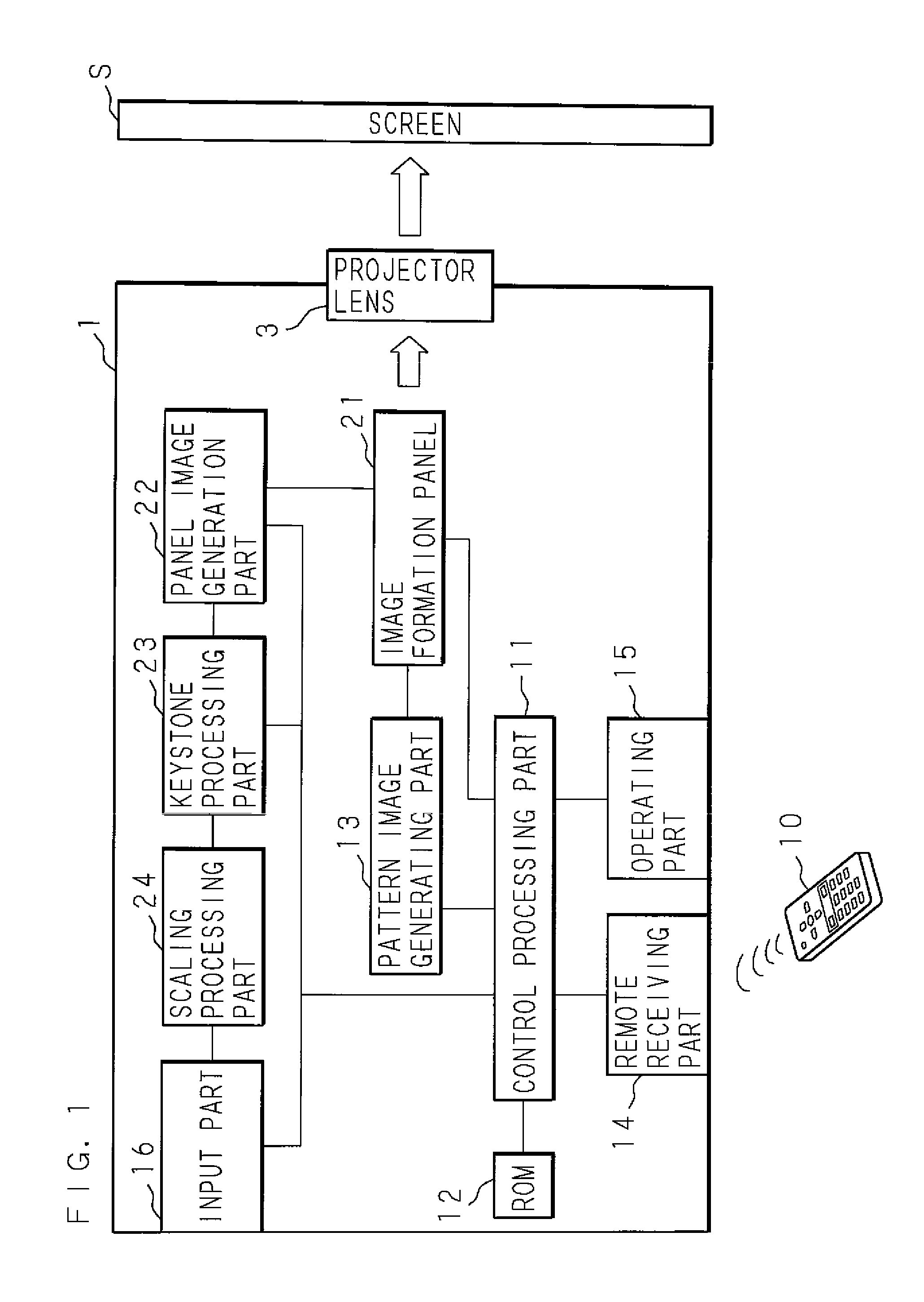
[0050]Hereinafter, based on the drawings illustrating embodiments of the present invention, the present invention will be specifically described. FIG. 1 is a block diagram showing the functions inside a projector according to the present invention. The projector 1 comprises a control processing part 11 composed of a processor carrying out arithmetic and a RAM for storing information for the arithmetic. The control processing part 11 is connected to a ROM 12 storing control programs, and performs a process to control entire operation of the projector 1 according to the control programs stored in the ROM 12. The control processing part 11 is connected to a remote receiving part 14 which receives a signal sent by using, e.g. infra-red radiation or electric wave from a remote controller (remote) 10 operated by the user, and an operating part 15 which composed of various kinds of switches and accepts various kinds of instructions for processing through the user's operation. The remote receiving part 14 and the operating part 15 are configured to accept various kinds of instructions for processing and perform a processing according to the accepted instructions for processing. Moreover, the projector 1 comprises a planar image formation panel 21 which is composed of a liquid crystal panel or a DMD, or the like. The image formation panel 21 has plural pixels constituted of liquid crystal, minute mirrors, etc, to form a panel image with a predetermined resolution defined by the number of pixels. The projector 1 projects light to the image formation panel 21, using a light source and an optical system which are not shown. Furthermore, the projector 1 comprises a projector lens 3 which projects to the outside the light projected to the image formation panel 21 and reflected by the image formation panel 21. The white arrow in FIG. 1 shows light. The light from the projector lens 3 is projected to an external screen (projection plane) S of the projector 1, and then a projection image is projected on a surface of the screen S. In addition, the projector 1 may be configured to project a projection image by projecting light passing through the image formation panel 21 that has formed a panel image.
[0051]The projector 1, furthermore, comprises an input part 16 to input image data from external devices, such as a television tuner or a PC. The input part 16 is connected to a scaling processing part 24 to scale an image created from input image data input to the input part 16, in accordance with the resolution of the image formation panel 21. The scaling processing part 24 is connected to a keystone processing part 23 to perform keystone correction for the image scaled by the scaling processing part 24. The keystone processing part 23 is connected to a panel image generation part 22 to generate a panel image including the image keystone-corrected by the keystone processing part 23. The panel image generation part 22 is connected to the image formation panel 21 to form the panel image generated by the panel image generation part 22.
[0052]The image formation panel 21 is, moreover, connected to a pattern image generation part 13 to generate a pattern image constituted of an outer frame or points at the four corners, which shows a range of the projection image. The projector 1 is configured to project an image showing a range of the projection image to the screen S, by making the image formation panel 21 to form the pattern image generated by the pattern image generation part 13. The input part 16 is connected to the control processing part 11, and information on the input image data is input into the control processing part 11. Moreover, the pattern image generation part 13, the keystone processing part 23, the panel image generation part 22, and the image formation panel 21 are connected to the control processing part 11, and their operations are controlled by the control processing part 11.
[0053]Next, description will be given to an image projection method according to the present invention, which is performed by the projector 1 comprising the configuration described above. The control processing part 11 sets an offset region and a displayable region in a range where the image formation panel 21 forms an image, according to an aspect ratio and resolution of a projection image to be projected based on the image data input to the input part 16. The offset region is a region where an original image for the projection image is not formed and the displayable region is a region where an original image for the projection image can be formed. The whole area of the image formation panel 21 is configured to be the displayable region, when the image formation panel 21 is configured to have an aspect ratio of 4:3, the aspect ratio of the projection image is 4:3, and the resolution of the projection image is higher than the resolution of the image formation panel 21. On the occasion when the projector 1 first projects the projection image, the image formation panel 21 forms a panel image that is the original image for projection displayed on the whole area of the displayable region. It is often the case that screen S is previously configured to have a predetermined aspect ratio, such as 4:3 or 16:9 and so on, in accordance with the aspect ratio of the projection image. When a projection image with the aspect ratio of 4:3 is projected to the screen S with the aspect ratio of 4:3, the projection image can be projected on the whole area of the screen S. However, the projection image projected by the projector 1 to the screen S is projected in a distorted shape from a rectangular shape, because the projector 1 is rarely put just in front of the screen S. Therefore, it is required, first of all, to correct the keystone distortion of the projection image by keystone correction.
[0054]FIG. 2 is a flowchart showing procedures for setting the keystone correction performed by the projector 1. The processing part 11 waits for acceptance of instructions to set a projection range, which shows a range where the projection image can be projected on the screen S (S11), as the instructions are given by a predetermined operation of the user to the operation part 15 or by a predetermined operation of users to the remote 10 to make the remote receiving part 14 receive a predetermined signal sent from the remote 10. When the control processing part 11 does not accept the instructions to set the projection range (S11: NO), the control processing part 11 keeps on waiting for acceptance of instructions. When the control processing part 11 accepts the instructions to set a projection range (S11: YES), the control processing part 11 makes the pattern image generation part 13 to generate a pattern image showing a range of the projection image with a specific aspect ratio, such as 4:3 and so on, and makes the image formation panel 21 to form the generated pattern image. The image showing a range of the projection image is projected to the screen S, by projecting light reflected by the image formation panel 21, from the projector lens 3 (S12). At that time, the projector 1 projects an image consisting of four luminescent spots corresponding to the four corners of the projection range, to the screen S. In addition, the projector may be configured to perform processing to project an image consisting of luminescent line corresponding to the outer frame of the projection range.
[0055]FIG. 3 is exemplary schematic views illustrating correspondence between a projecting range on the screen S and a pattern image formed by the image formation panel 21. FIG. 3 (a) shows an image projected on the screen S, in the case that the pattern image is formed on the whole area of image formation panel 21. FIG. 3 (b) shows the image formation panel 21 forming the pattern image on the whole area of the image formation panel 21. Filled circles in the figures show luminescent spots corresponding to the four corners of the projection range. As shown in FIG. 3 (a), generally, a range where the whole area of the image formation panel 21 is projected on the screen S, does not correspond to a range where an image can be projected on the screen S, and the shape of the range is distorted from a rectangular shape. When visually recognizing such an image as shown in FIG. 3 (a), the user inputs instructions to deform the projection range by displacing the respective luminescent spots corresponding to the four corners of the projection range, through operation of the operation part 15 or the remote 10.
[0056]After the step S12 is completed, the control processing part 11 waits for acceptance of instructions to deform the projection range (S13). When the control processing part 11 accepts the instructions to deform the projection range (S13: YES), the control processing part 11 displaces positions of the luminescent spots projected on the screen S, and thereby deforms the projection range, by displacing each position of the luminescent spot involved in the pattern image generated by the pattern image generation part 13 (S14). When the control processing part 11 does not accept instructions to deform the projection range at the step S13 (S13: NO), or when the step S14 is completed, the control processing part 11 waits for acceptance of instructions to establish a projection range, to be given by the user through operation of the operation part 15 or the remote 10 (S15). When the control processing part 11 does not accept instructions to establish the projection range (S15: NO), the control processing part 11 returns procedures to the step S13. When the control processing part 11 accepts instructions to establish the projection range (S15: YES), the control processing part 11 establishes a projection range corresponding to the pattern image generated by the pattern image generation part 13 (S16).
[0057]FIG. 3 (c) shows a projection range established on the screen S. The user operates the projector 1 to make the projection range with rectangular shape, as shown in the figure, while visually recognizing the projected image. When the aspect ratio of the projection range is the same as the aspect ratio of the screen S, the whole area of the screen S can be utilized as the projection range, by displacing the luminescent spots corresponding to the four corners of the projection range at four corners of the screen S, as shown in the figure. FIG. 3 (d) shows the image formation panel 21 firming a pattern image corresponding to the established projection image on the screen S. The luminescent spots on the image formation panel 21 corresponding to the four corners of the projection range moves, in accordance with the displacement of the luminescent spots corresponding to the four corners of the projection range on the screen S to form the projection range into a rectangular shape. The range framed by the four luminescent spots on the image formation panel 21 is a range corresponding to the projection range on the image formation panel 21, and an image formed in this range is projected to the projection range on the screen S.
[0058]The control processing part 11, then, acquires coordinates of a range corresponding to the established projection range, on a panel coordinate system that defines a position of a spot on the image formation panel 21 (S17). The control processing part 11 previously defines a panel coordinate system. For example, when the image formation panel 21 is configured with 1024×768 pixels, the control processing part 11 defines a coordinate of a pixel at upper left corner on the image formation panel 21 as (0, 0), and a coordinate of each pixel on the image formation panel 21 as (x, y) where x is 0≦x≦1024 and y is 0≦y≦768. The control processing part 11 acquires coordinates of a range corresponding to the established projection range, by acquiring coordinates of pixels at the positions of the luminescent spots on the image formation panel 21 corresponding to the four corners of the projection range, on the defined panel coordinate system.
[0059]The control processing part 11, then, acquires coordinates of the established projection range on a screen coordinate system (projection plane coordinate system) that defines a position of a spot on the screen S (S18). At this time, the control processing part 11 sets the values of an aspect ratio and a resolution of the projection range the same as the aspect ratio and the resolution of the displayable region of the image formation panel 21 at the time the projection range is set to define the screen coordinate system. For example, when the whole area of an image formation panel with 1024×768 pixels is the displayable region, the control processing part 11 defines the screen coordinate system to make the respective coordinates of the four corners of the projection range to be (0, 0), (0, 768), (1024, 0) and (1024, 768). In addition, any given coordinate system may be set as a screen coordinate system. The control processing part 11 can acquire the coordinates of the projection range on the screen coordinate system, by acquiring the coordinates of the four corners of the projection range as just described.
[0060]The control processing part 11 calculates conversion parameters for a predetermined conversion formula for mutually converting a position on the panel coordinate system and a position on the screen coordinate system by projecting a position on the image formation panel 21 to a surface on the screen S (S19). This conversion is a coordinate conversion based on projective transformation between the panel coordinate system and the screen coordinate system. Known formulas include a common conversion formula to convert coordinates from a panel coordinate system to a screen coordinate system and a common conversion formula to convert coordinates from a screen coordinate system to a panel coordinate system using the projective transformation. The control program stored by ROM 21 includes these conversion formulas. The control processing part 11 calculates conversion parameters for a the conversion formula, based on correspondence between coordinates on the panel coordinate system corresponding to the four corners of the projection range and coordinates on the screen coordinate system. The control processing part 11 stores the calculated conversion parameters and completes the process for the projection range setup.
[0061]After the completion of the projection range setup, the projector 1 performs keystone correction for a projection image to project the projection image within the set up projection range, in the condition that the aspect ratio and the resolution of the projection image is not changed. FIG. 4 is the flowchart showing procedures of the process that the projector 1 performs keystone correction and projects an image. When image data is input from external to the input part 16 (S21), the scaling processing part 24 scales an image based on the input image data, according to the resolution of the image formation panel 21 (S22). For example, when an image with 1280×720 resolution is input, the scaling processing part 24 reduce the image to an image with 1004×768 resolution, corresponding to the image formation panel 21. The control processing part 11, then, makes the keystone processing part 23 deform the image scaled by the scaling processing part 24, to fall the image into a range on the image formation panel 21 corresponding to the projection range (S23). The keystone processing part 23, as shown in FIG. 10 (b), generates a sub-image including the deformed image (S24). The panel image generation part 22 generates a panel image including a portion corresponding to the offset region of the image formation panel21 and a panel image including the sub-image generated by the keystone processing part 23 (S25). Since the image formation panel 21 does not have an offset region and the whole area of the image formation panel 21 is the displayable region in the case that the aspect ratio of the projection image is the same as the aspect ratio of the image formation panel 21, the panel image matches the sub-image. The control processing part 11 makes the image formation panel 21 form the panel image generated by the panel image generation part 22 (S26), projects the keystone-corrected projection image corrected for keystone correction to the screen S, by projecting from the projector lens 3 the light reflected by the image formation panel 21 which has formed the panel image (S27). Thus, the projector 1 completes the process, and repeats the process every time the image data is input into the input part 16.
[0062]The projector 1, according to the present invention) performs processing to project a projection image with changed details of keystone correction, when it is required to project the projection image with a different aspect ratio or a different resolution from the aspect ratio and the resolution of the set up projection range. This situation is applied to the case that the input image data represents an image with a different aspect ratio from the aspect ratio of the set up projection range, the case that the input image data represents an image with a lower resolution than the resolution of the set up projection range, or the case that the projector 1 accepts instructions from the user to change the aspect ratio or the resolution of the projection image. FIG. 5 and FIG. 6 are flowcharts showing procedures to change the details of the keystone correction performed by the projector 1.
[0063]The control processing part 11 waits for input of image data into the input part 15 to make the aspect ratio or the resolution of the projection image to be different from the set up projection range (S301). When there is no input of image data with a different aspect ratio or a different resolution (S301: NO), the control processing part 11 waits for acceptance of instructions to change the aspect ratio or the resolution of the projection image given by the predetermined operation of the user to the operation part 15 or the remote 10 (S302). When there is no acceptance of the instructions (S302: NO), the control processing part 11 returns the process to the step S301. When there is an input of image data with a different aspect ratio or a different resolution at the step S301 (S301: YES), or when there is acceptance instructions to change the aspect ratio or the resolution of the projection image (S302: YES), the control processing part 11 makes the image formation panel 21 set an offset region and a displayable region, corresponding to the changed aspect ratio or resolution of the projection image (S303). The control processing part 11, then, acquires coordinates for the set displayable region in the panel coordinate system (S304).
[0064]FIG. 7 is a schematic view showing the processing to change the details of keystone correction in a panel coordinate system and a screen coordinate system. In the figures, an exemplar case is showed where the aspect ratio of a projection image is changed from 4:3 to 16:9. In FIG. 7 (a), broken lines show a range of the image formation panel 21 on the panel coordinate system, and solid lines show a range of the displayable region. As the aspect ratio is changed from 4:3 to 16:9, the offset regions are set at upper and lower portions of the image formation panel 21. Then, it sets displayable region with the aspect ratio of 16:9, which is smaller than the whole area of the image formation panel 21. The control processing part 11 acquires coordinates of the displayable region by acquiring, for example, coordinates of the four corners of the displayable region. The displayable region set at this process corresponds to the shape of the image before keystone correction.
[0065]The control processing part 11, then, converts the coordinates of the displayable region in the panel coordinate system to the coordinates in the screen coordinate system, with the use of the conversion formula and the conversion parameter to convert coordinates from the panel coordinate system to the screen coordinate system (S305). In FIG. 7 (b), broken lines show a projection range in the screen coordinate system, and solid lines show a range corresponding to a displayable region. Because of the offset regions, a range corresponding to the displayable region is reduced in the up-and-down direction than the projection range. The control processing part 11, then, acquires a coordinate for a center point of the projection range on the screen coordinate system (S306). At this time, the control processing part 11 averages coordinates for the four corners of the projection range in the screen coordinate system, and then acquires the coordinate for the center point. The control processing part 11, then, generates a first straight line passing the center point with an inclining angle whose value is the same as the changed aspect ratio of the projection image, and a second straight line passing the center point with an inclining angle whose value is a negative number obtained by multiplying the changed aspect ratio of the projection image by −1 (S307). In FIG. 7 (c), the first straight line and the second straight line are shown. When the changed aspect ratio of the projection image is 16:9, the inclining angle of the first straight line is 9/16 and the inclining angle of the second straight line is − 9/16.
[0066]The control processing part 11, then, calculates coordinates of intersecting points where the first straight line and the second straight line intersect with edges of a range corresponding to the displayable region on the screen coordinate system (S308). The control processing part 11, then, calculates distances on the screen coordinate system from the center point to each intersecting point whose coordinates have been calculated (S309), and selects one intersecting point whose distance is the shortest of all the calculated distances (S310). The control processing part 11, then, calculates distances from the center point to the edges of the projection range on the first straight line and on the second straight line, in the screen coordinate system (S311), and judges whether the distance from the center point to the selected intersecting point is equal to or shorter than the distance from the center point to the edge of the projection range (S312). When the distance from the center point to the selected intersecting point is equal to or shorter than the distance from the center point to the edge of the projection range (S321: YES), the control processing part 11 acquires four points on the first straight line and on the second straight line whose distances to the center point are equal to the distance from the center point to the selected intersection point, on the screen coordinate system (S313). When the distance from the center point to the selected intersecting point is longer than the distance from the center point to the edge of the projection range (S321: NO), the control processing part 11 acquires four points, on the screen coordinate system, where the edges of the projection range intersect with the first straight line and on the second straight line (S314).
[0067]After the step S313 or the step S314 is completed, the control processing part 11 specifies a rectangular area with the acquired four points as four corners in the screen coordinate system (S315). In FIG. 7 (d), dashed lines show a range of the rectangular area. The aspect ratio of the rectangular area is equal to the changed aspect ratio of the projection image, because the rectangular area has four corners consisting of four points, whose distances from the center point are equal to each other, on the first straight line with the changed aspect ratio of the projection image as the inclining angle and on the second straight line with the negative value of the changed aspect ratio of the projection image as the inclining angle. Furthermore, the rectangular area falls in a range corresponding to the displayable region and the projection range, because the rectangular area includes at its four corners the points whose distances from the center point are the shortest of all the intersecting points where the first straight line and the second straight line intersect with the edges of a range corresponding to the displayable region or with the edges of the projection range. Therefore, it is possible to project the projection image with the changed aspect ratio, by projecting an image within the specified rectangular area on the screen S.
[0068]The control processing part 11, then, converts coordinates of the rectangular area on the screen coordinate system to coordinates on the panel coordinate system, with the use of the conversion formula and the conversion parameter for converting coordinates from the screen coordinate system to the panel coordinate system (S316). FIG. 7 (e) shows ranges corresponding to the displayable region and the rectangular area, in the panel coordinate system. Dashed lines show a range corresponding to the rectangular area on the panel coordinate system. It is possible to form an original image for the projection image within this range, because the range corresponding to the rectangular area falls in the displayable region even on the panel coordinate system.
[0069]The control processing part 11, then, acquires a position of the range corresponding to the rectangular area within the displayable region after subtracting a portion corresponding to offset regions of the image formation panel 21 from coordinates in the panel coordinate system, and then calculates a deformation parameter required for a predetermined deformation formula that deforms a shape of an image corresponding to the whole displayable region to be a shape of the range corresponding to the rectangular area for keystone correction (S317). This deformation formula is similar to the conversion formula that converts a position on the screen coordinate system to a position on the panel coordinate system, but differs in a value of the parameter from the conversion formula. It is possible to deform an image so as to fit an original image for the projection image within the range corresponding to the rectangular area and to perform keystone correction, by converting points on an image before keystone correction to points within a region corresponding to the rectangular area, utilizing the deformation formula and the deformation parameter. The control processing part 11 stores the calculated deformation parameter, and completes the processing to change the details of keystone correction.
[0070]After changing the details of keystone correction, the projector 1 projects an image according to the changed details of keystone correction, through the same process shown by the flowchart in FIG. 4. FIG. 8 shows schematic views illustrating procedures to project an image with an aspect ratio of 16:9 using an image formation panel 21 whose aspect ratio is 4:3. FIG. 9 shows schematic views illustrating procedures to project an image whose resolution is less than a projecting range. Hereinafter, the process is explained, with the use of FIG. 8, FIG. 9 and FIG. 4, for the projector 1 to project an image after changing the details of keystone 6 correction. FIG. 8 (a) shows a condition of the image formation panel 21 when the aspect ratio of the projection image is 16:9. Offset regions are set at upper and lower portions of the image formation panel 21, and a displayable region is set with the aspect ratio of 16:9. For example, when the resolution of the image formation panel 21 is 1024×768, the resolution of the displayable region is 1024×576 by subtracting the offset regions from the image formation panel 21. FIG. 9 (a) shows a condition of the image formation panel 21 when the resolution of the projection image is reduced. Offset regions are set at peripheral portions of the image formation panel 21, and the displayable region is set with the number of pixels corresponding to the reduced resolution. For example, when the resolution of the projection image is 768×576, the displayable region is set with 768×576 pixels. In FIG. 8 (a) and FIG. 9 (a), broken lines show a range corresponding to the rectangular area, which is acquired by the process shown by the flowchart in FIG. 5 and FIG. 6.
[0071]Image data is input from external to the input part 16 (S21). The scaling processing part 24 scales an image based on the input image data, according to the resolution of the displayable region of the image formation panel 21 (S22). FIG. 8 (b) and FIG. 9 (b) show the scaled image, according to the resolution of the displayable region. In FIG. 8 (b), the aspect ratio of the image is 16:9. In FIG. 9 (b), the aspect ratio of the image is 4:3 which is reduced in accordance with the lower resolution. The control processing part 11, then, makes the keystone processing part 23 deform the scaled image with the use of the deformation formula and the deformation parameter (S23). The keystone processing part 23 generates a sub-image including the deformed image (S24). FIG. 8 (c) and FIG. 9 (c) show exemplificative sub-images. Image regions, shown in the figures, correspond to the deformed image by keystone correction, and finally correspond to the projection region. The panel image generation part 22 generates a portion corresponding to the offset region and a panel image including the sub-image (S25). FIG. 8 (d) and FIG. 9 (d) show exemplificative is panel images. The panel images include portions corresponding to the offset regions and the sub-image, and locate the image region at a range corresponding to the rectangular area. The control processing part 11, then, makes the image formation panel 21 form the panel image generated by the panel image generation part 22 (S26), and projects the projection image which is keystone-corrected in accordance with the changed details to the screen S, by projecting from the projector lens 3 the light reflected by the image formation panel 21 (S27). FIG. 8 (e) and FIG. 9 (e) show exemplificative projection images. In the figures, broken lines show projection ranges. In FIG. 8 (e), a projection image is projected with the aspect ratio of 16:9, within the projection range. In FIG. 9 (e), a scaled projection image is projected with reduced resolution, within the projection range.
[0072]As described above, in this invention, the projector 1 sets the projection range with a given aspect ratio on the screen S and acquires a range corresponding to the projection range on the image formation panel 21, when the projector 1 projects the projection image to the screen S. Furthermore, the projector 1 performs keystone correction by forming an original image for projection within a range acquired on the image formation panel 21 and projects the rectangular projection image to the screen S. When the aspect ratio and the resolution of the projection image are not changed, the projector 1 deforms the image to fall within a range corresponding to the projection range on the image formation panel 21, makes the image formation panel 21 form the panel image including the deformed image, and projects the projection image. By projecting the deformed image in this way, it is possible to project the projection image adjusted to be rectangular shape by keystone correction, in the whole area of the projection range with the given aspect ratio.
[0073]Moreover, in the present invention, the projector 1 obtains the conversion parameters required for the conversion formulas for mutual conversion between the panel coordinate system and the screen coordinate system based on the relationship between the coordinates of the projection range in the screen coordinate system and the coordinates of the range corresponding to the projection range in the panel coordinate system. When the aspect ratio and the resolution of the projection image are changed, the projector 1 converts the coordinates of the displayable region in the panel coordinate system according to the aspect ratio and the resolution to the coordinates in the screen coordinate system, and generates the rectangular area with a desired aspect ratio within a range corresponding to the displayable region in the screen coordinate system and the portions included in the projection range. Furthermore, the projector 1 converts the coordinates of the rectangular area in the screen coordinate system to the coordinates of a range corresponding to the rectangular area in the panel coordinate system, and makes the image formation panel 21 to form the image within a range corresponding to the rectangular area. By projecting the image formed within a range corresponding to the rectangular area on the image formation panel 21, it is possible to project the projection image within the rectangular area on the screen S. The projector 1 deforms the image so that the original image for projection falls within a range corresponding to the rectangular area on the image formation panel 21, makes the image formation panel 21 form the panel image including the deformed image, and projects the projection image. Thus, it is possible to project the projection image within the rectangular area on the screen S. Therefore, it is possible to project the projection image with the changed aspect ratio and with a size corresponding to the changed resolution. Thus, even when an aspect ratio or a resolution of the projection image is changed after setting keystone correction, the projector 1 can promptly project the projection image with a desired aspect ratio and size according to a desired resolution, without performing setting for keystone correction again Especially, because there is no need for the user to take time and effort for operating the projector to perform setting of keystone correction, a shape of the projection image is automatically changed even when an aspect ratio and a resolution of an image corresponding to a input image data are changed. Besides, the aspect ratio and the resolution of the projection image can be changed easily, and thus, improved usability of the projector can be provided.
[0074]Moreover, in the present invention, when setting the rectangular area within a region corresponding to the displayable region and a portion included in the projection range in the screen coordinate system, the projector 1 sets the rectangular area with a desired aspect ratio, so that one of the points at four corners centering around the central point of the projection range contacts an edge of a region corresponding to the displayable region or an edge of the projection range. Therefore, the rectangular area with the desired aspect ratio can be set, with the largest possible size, at the center of the projection range. Thus, the projector 1 can project projection images with several aspect ratio, with a high visibility size for the user without reducing the size of the projection image to become unduly smaller than required.
[0075]In addition, in the embodiments, while the projector according to the present invention is configured to set the projection range on the screen S, in response to the user's operation for setting keystone correction, the present invention should not be limited thereto, but the projector may be configured to pick up a pattern image projected on the screen S, and to set the projection range automatically so that the picked up pattern image becomes rectangular shape. Even in this case, the projector according to the present invention can project the projection image with a desired aspect ratio and a desired resolution within the set projection range, without performing the setting for keystone correction again, every time the aspect ratio or the resolution of the projection image is changed.
[0076]Moreover, in the embodiments, it is illustrated that the projector 1 projects the projection image to the screen S, but, even if the projection plane according to the present invention is configured to be different configuration, such as a house wall the projector 1 according to the present invention is configured to be able to project the keystone-corrected projection image by performing with the same processing as described above. Moreover, in the embodiments, illustration is given only about the case that the displayable region on the image formation panel 21 is reduced in response to the change of the aspect ratio or the resolution of the projection image, but even if the displayable region on the image formation panel 21 is enlarged in response to the change of the aspect ratio or the resolution of the projection image, the projector 1 according to the present invention is able to perform similar processing as described above. Even in this case, the projector according to the present invention can project a projection image with a desired aspect ratio and a desired resolution within the set projection range.
PUM


Description & Claims & Application Information
We can also present the details of the Description, Claims and Application information to help users get a comprehensive understanding of the technical details of the patent, such as background art, summary of invention, brief description of drawings, description of embodiments, and other original content. On the other hand, users can also determine the specific scope of protection of the technology through the list of claims; as well as understand the changes in the life cycle of the technology with the presentation of the patent timeline. Login to view more.