
Printed circuit board and manufacturing method thereof

a printed circuit board and manufacturing method technology, applied in the direction of printed circuit aspects, resist details, electrical apparatus construction details, etc., can solve the problems of short circuiting between circuits and improper contact, surface of printed circuit boards exposed to remnant solder, solder bridges, etc., to achieve sufficient attachment area and strengthen the adhesion of pads

Inactive Publication Date: 2009-01-29
SAMSUNG ELECTRO MECHANICS CO LTD
View PDF10 Cites 41 Cited by
  • Summary
  • Abstract
  • Description
  • Claims
  • Application Information

AI Technical Summary

Benefits of technology

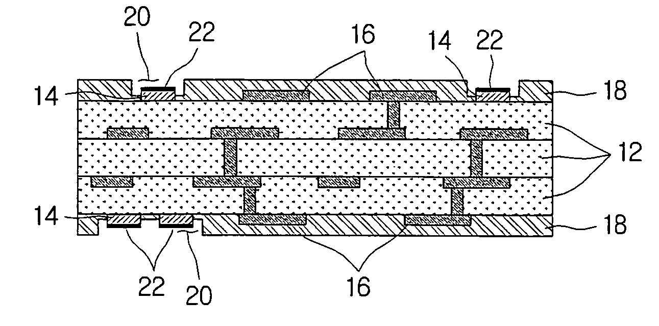
[0010]An aspect of the invention is to provide a printed circuit board and a method of manufacturing the printed circuit board, in which a sufficient amount of attachment area is ensured for the pads and the solder resist, to strengthen the adhesion of the pads.
[0018]With certain embodiments of the invention, a sufficient amount of attachment area can be ensured for the pads and the solder resist, to strengthen the adhesion of the pads. Also, the adhesion can be increased between the electronic components and the printed circuit board, and heat release characteristics can be improved.

Problems solved by technology

Such increased number of I / O and fine pitch of circuit patterns can become causes of short circuiting between circuits and improper contact.
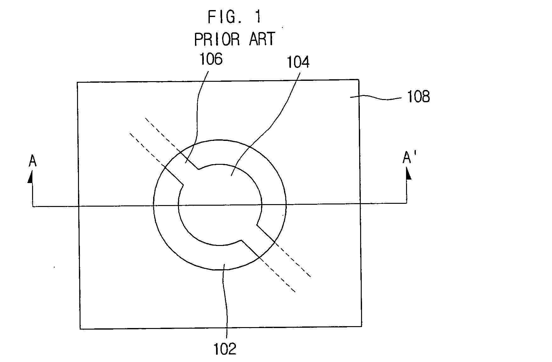
In particular, when mounting electronic components on a printed circuit board, the surface of the printed circuit board is exposed to remnant solder, which can create undesired contacts, or solder bridges.
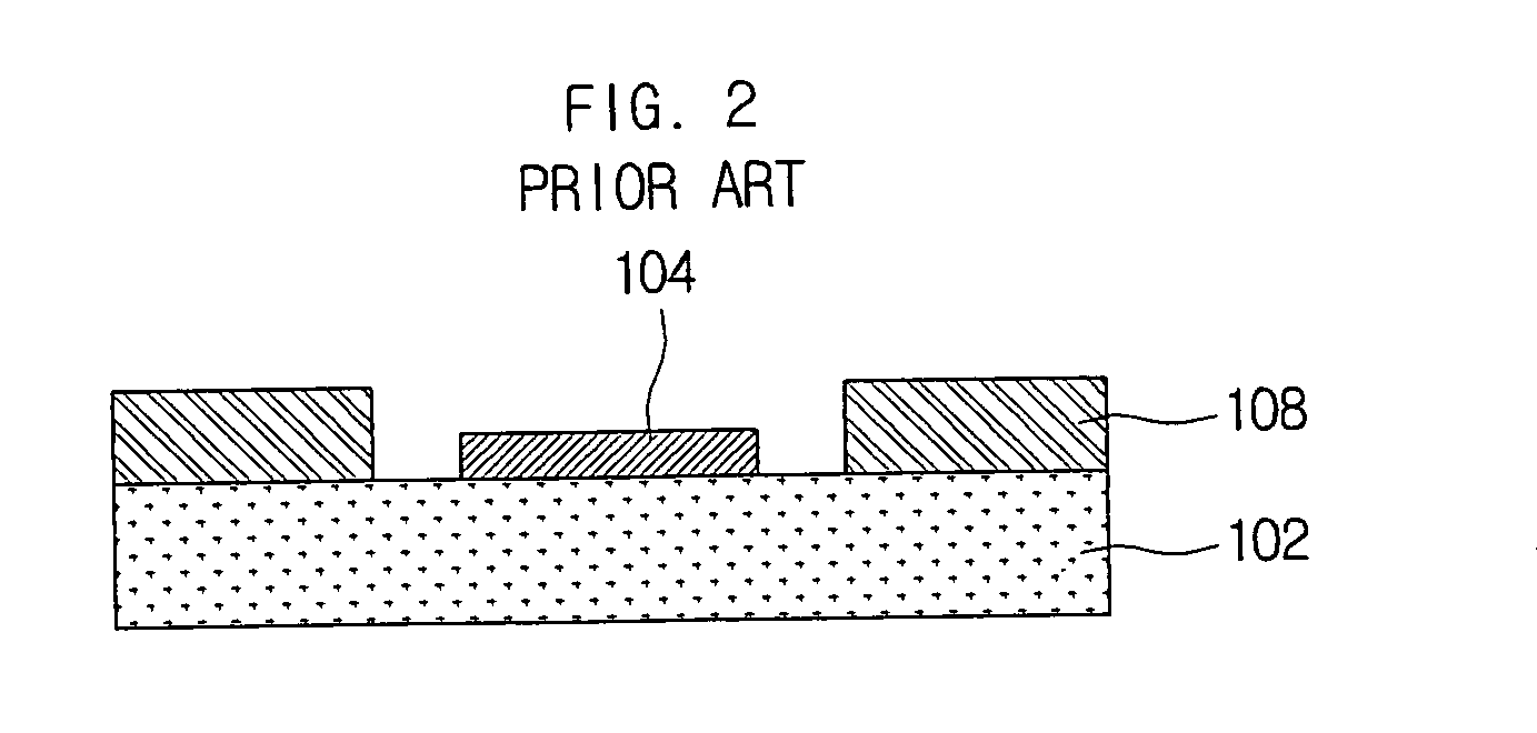
Also, since the attachment areas are small, there is a risk that the adhesion of the pads 104 will be weakened.

Method used


Image

  • Printed circuit board and manufacturing method thereof
  • Printed circuit board and manufacturing method thereof
  • Printed circuit board and manufacturing method thereof

Examples


Embodiment Construction

[0028]As the invention allows for various changes and numerous embodiments, particular embodiments will be illustrated in drawings and described in detail in the written description. However, this is not intended to limit the present invention to particular modes of practice, and it is to be appreciated that all changes, equivalents, and substitutes that do not depart from the spirit and technical scope of the present invention are encompassed in the present invention. In the description of the present invention, certain detailed explanations of related art are omitted when it is deemed that they may unnecessarily obscure the essence of the invention.

[0029]While such terms as “first,”“second,” etc., may be used to describe various components, such components must not be limited to the above terms. The above terms are used only to distinguish one component from another.

[0030]The terms used in the present application are merely used to describe particular embodiments, and are not inte...


PUM

PropertyMeasurementUnit
heat-resistantaaaaaaaaaa
sizeaaaaaaaaaa
sizesaaaaaaaaaa

Abstract

A printed circuit board and a method of manufacturing the printed circuit board are disclosed. A printed circuit board, which includes an insulation layer, a circuit pattern formed on a surface of the insulation layer that includes at least one pad, and a solder resist which covers the circuit pattern, and in which an opening is formed that exposes a portion of a side and a surface of the pad, can ensure a sufficient amount of attachment area for the pads and the solder resist, to strengthen the adhesion of the pads. Also, the adhesion can be increased between the electronic components and the printed circuit board, and heat release characteristics can be improved.

Description

CROSS-REFERENCE TO RELATED APPLICATIONS[0001]This application claims the benefit of Korean Patent Application No. 10-2007-0075185 filed with the Korean Intellectual Property Office on Jul. 26, 2007, the disclosure of which is incorporated herein by reference in its entirety.BACKGROUND[0002]1. Technical Field[0003]The present invention relates to a printed circuit board and a method of manufacturing the printed circuit board.[0004]2. Description of the Related Art[0005]With advances in the electronics industry, portable electronic products, including products for cell phones and DMB (digital multimedia broadcasting), are becoming smaller and more highly functionalized, which in turn is creating a demand for electronic components that are subminiature in size, highly integrated, multi-functionalized, and high in performance. According to the higher levels of integration of electronic components, the number of I / O (input / output) is increasing, so that there are demands for increased nu...

Claims


Application Information

Patent Timeline
Patent Type & Authority Applications(United States)
IPC IPC(8): H05K1/00H05K3/00
CPCH05K3/0032H05K3/3452Y10T29/49165H05K2203/0594H05K2201/09845H05K1/02
Inventor CHO, CHUNG-WOOLEE, JONG-JINCHO, SOON-JINLEE, YONG-DUKYOO, KI-YOUNGLEE, WOO-YOUNGKIM, CHIN-KWANKIM, JONG-YONGJEON, DONG-JU
Owner SAMSUNG ELECTRO MECHANICS CO LTD
Learn More