Crest factor reduction

a technology of crest factor and crest factor, applied in the direction of amplifiers, electrical devices, transmission, etc., can solve the problems of low efficiency of power amplifiers, inability to reduce the crest factor,

Inactive Publication Date: 2009-01-29
AVAGO TECH WIRELESS IP SINGAPORE PTE
View PDF11 Cites 44 Cited by
  • Summary
  • Abstract
  • Description
  • Claims
  • Application Information

AI Technical Summary

Problems solved by technology

For the transmitter amplifier, this is undesirable since the amplifier needs to be adjusted so that it can accommodate the peak signals and yet spends most of its time outputting signals at a lower level.
Typically, this leads to low efficiency for the power amplifier.
However, the determination of the window can be computationally complex and time consuming, and the squelching can distort signals beyond acceptable limits particularly in multi-carrier systems.

Method used


Image

  • Crest factor reduction
  • Crest factor reduction
  • Crest factor reduction

Examples


Embodiment Construction

[0022]The invention can be implemented in numerous ways, including as a process, an apparatus, a system, a composition of matter, a computer readable medium such as a computer readable storage medium or a computer network wherein program instructions are sent over optical or communication links. In this specification, these implementations, or any other form that the invention may take, may be referred to as techniques. A component such as a processor or a memory described as being configured to perform a task includes both a general component that is temporarily configured to perform the task at a given time or a specific component that is manufactured to perform the task. In general, the order of the steps of disclosed processes may be altered within the scope of the invention.

[0023]A detailed description of one or more embodiments of the invention is provided below along with accompanying figures that illustrate the principles of the invention. The invention is described in conne...


PUM


Abstract

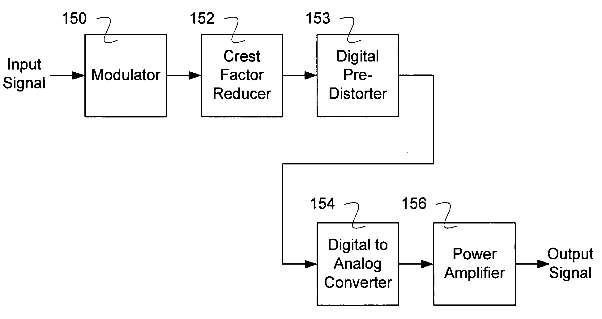
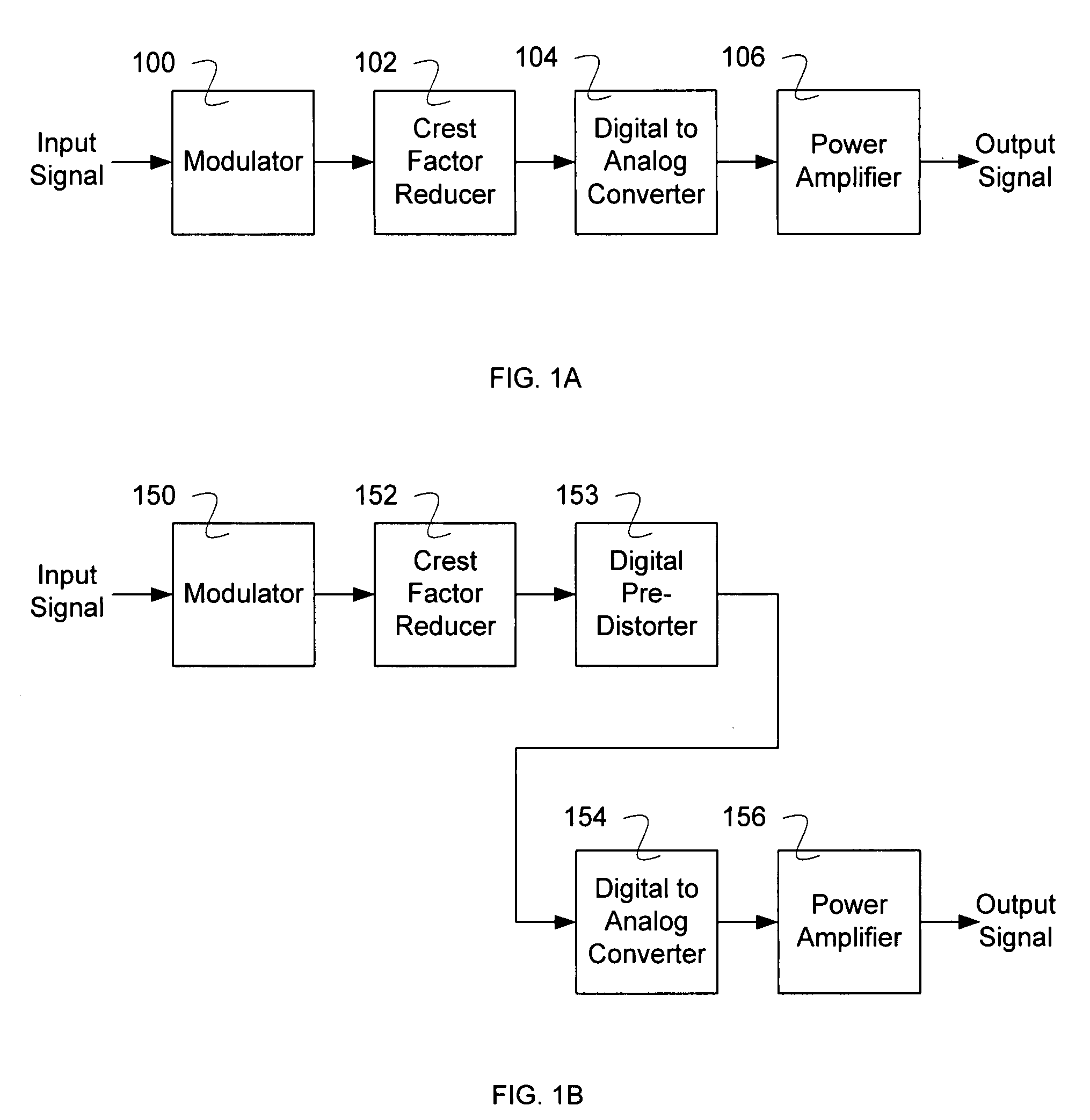
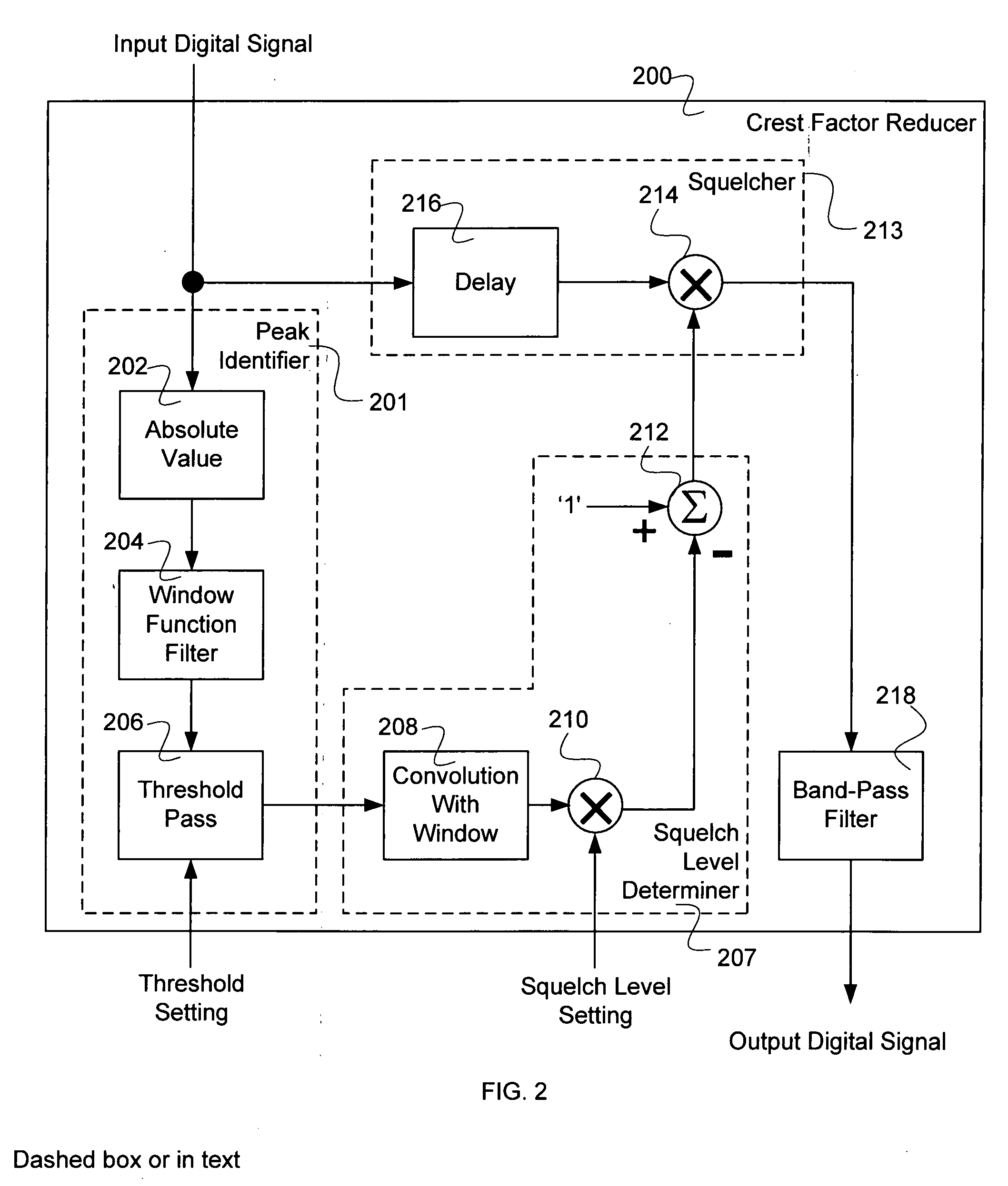
A device for generating a crest factor reduced signal is disclosed. The device comprises an interface for receiving an input signal; a peak identifier for identifying one or more peak regions of the input signal; a squelch level determiner for determining a reduction of the input signal near the one or more peak regions; a squelcher for reducing the one or more peak regions of the input signal as indicated by the squelch level determiner; and an interface for outputting a crest factor reduced signal. The crest factor reduced signal has a reduced dynamic range due to the reduction of the one or more peak regions of the input signal. The crest factor reduced signal also has been filtered to reduce undesired frequency components by: calculating a difference between a squelched signal from the squelcher and the input signal, band-pass filtering the difference to generate a result, and summing the result with the input signal that has been delayed.

Description

BACKGROUND OF THE INVENTION[0001]Information in contemporary communication systems can be carried by modulated signals that go from employing only a single carrier to modulations that employ multiple carriers. These modulated signals are typically amplified prior to being transmitted either over a wired media or wirelessly, where the amplifier's performance must maintain linearity to ensure appropriate signal integrity.[0002]When a signal is narrow band, such as is the case in a single carrier modulation scheme, the desired transmitted signal has almost a constant envelope where the ratio of the signal peak to the signal average is reasonably low. For the transmitter amplifier, this is desirable since the amplifier can be efficiently used in terms of its output power capabilities. However, when the signal is broad band, as is true when multiple carriers are used (e.g., when orthogonal frequency division modulation or wideband code division multiple access modulation), the desired tr...

Claims


Application Information

Patent Timeline
Patent Type & Authority Applications(United States)
IPC IPC(8): H04B1/10H04B1/06
CPCH04B2001/0441H04B1/0475H03F1/3223H03F3/24
Inventor BATRUNI, ROY G.
Owner AVAGO TECH WIRELESS IP SINGAPORE PTE
Why Eureka
Try Eureka