

Endoscope Insertion Portion and Endoscope System
- Summary
- Abstract
- Description
- Claims
- Application Information
AI Technical Summary
Benefits of technology
Problems solved by technology
Method used
Image

Examples
first embodiment
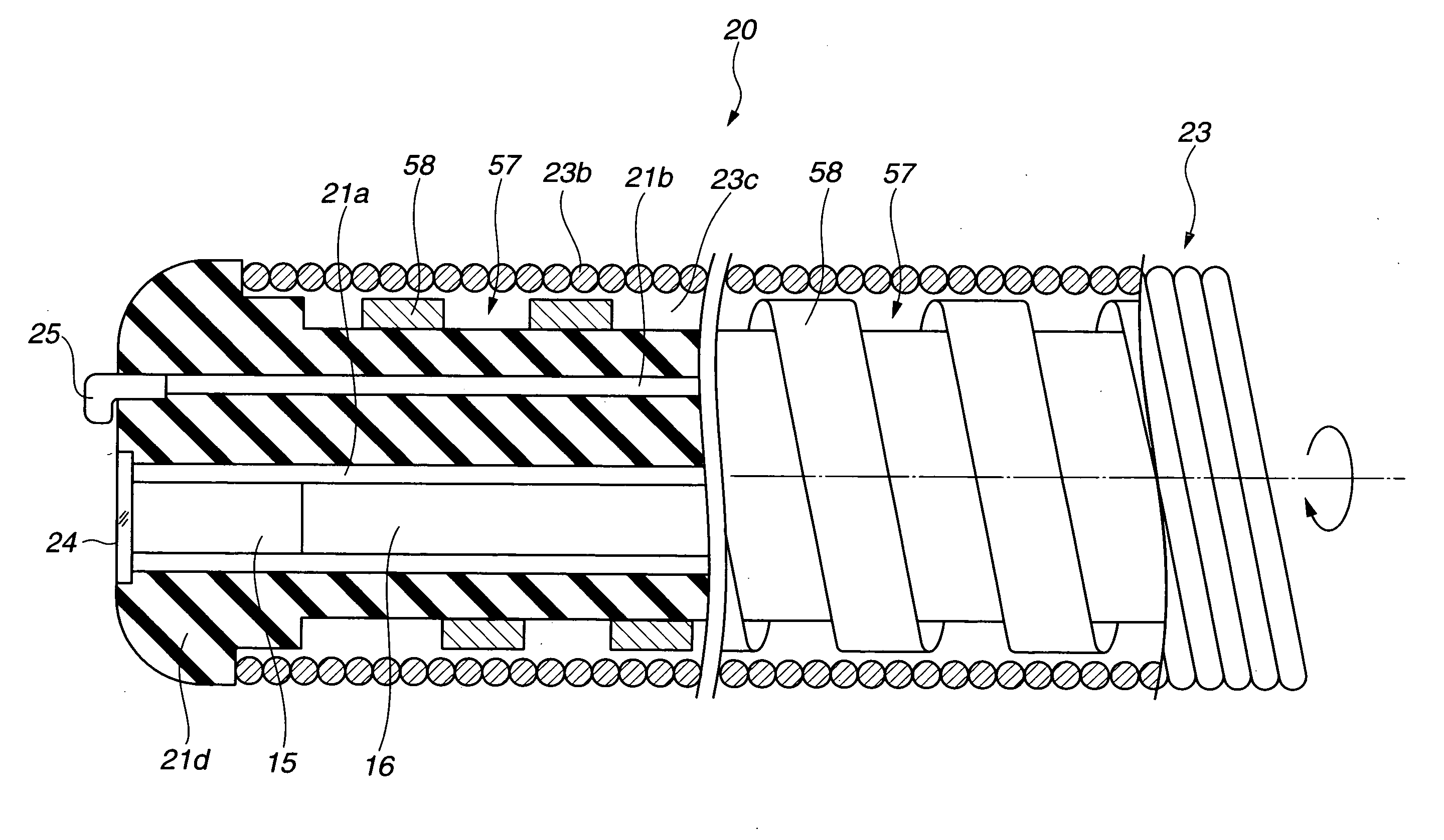
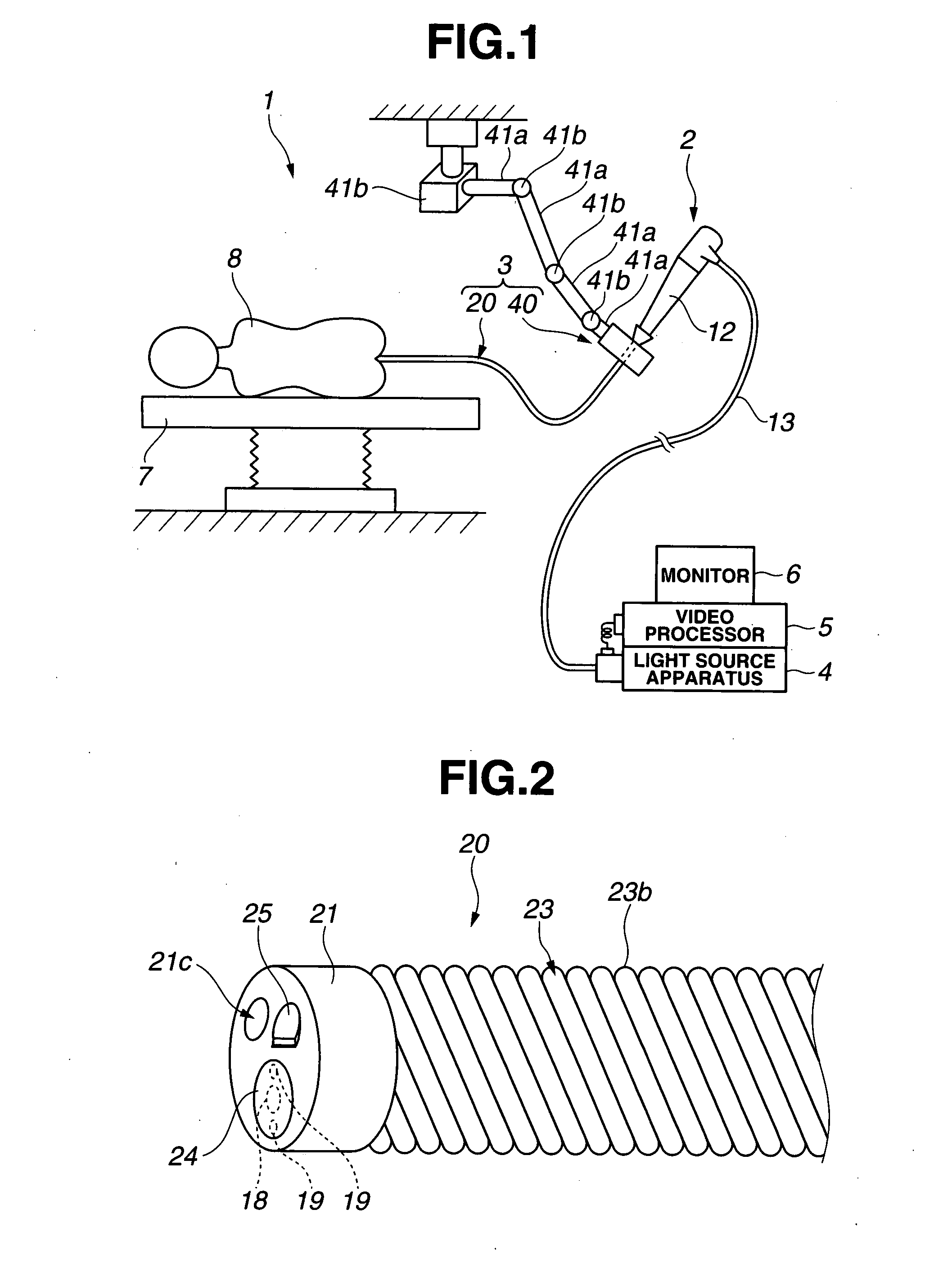
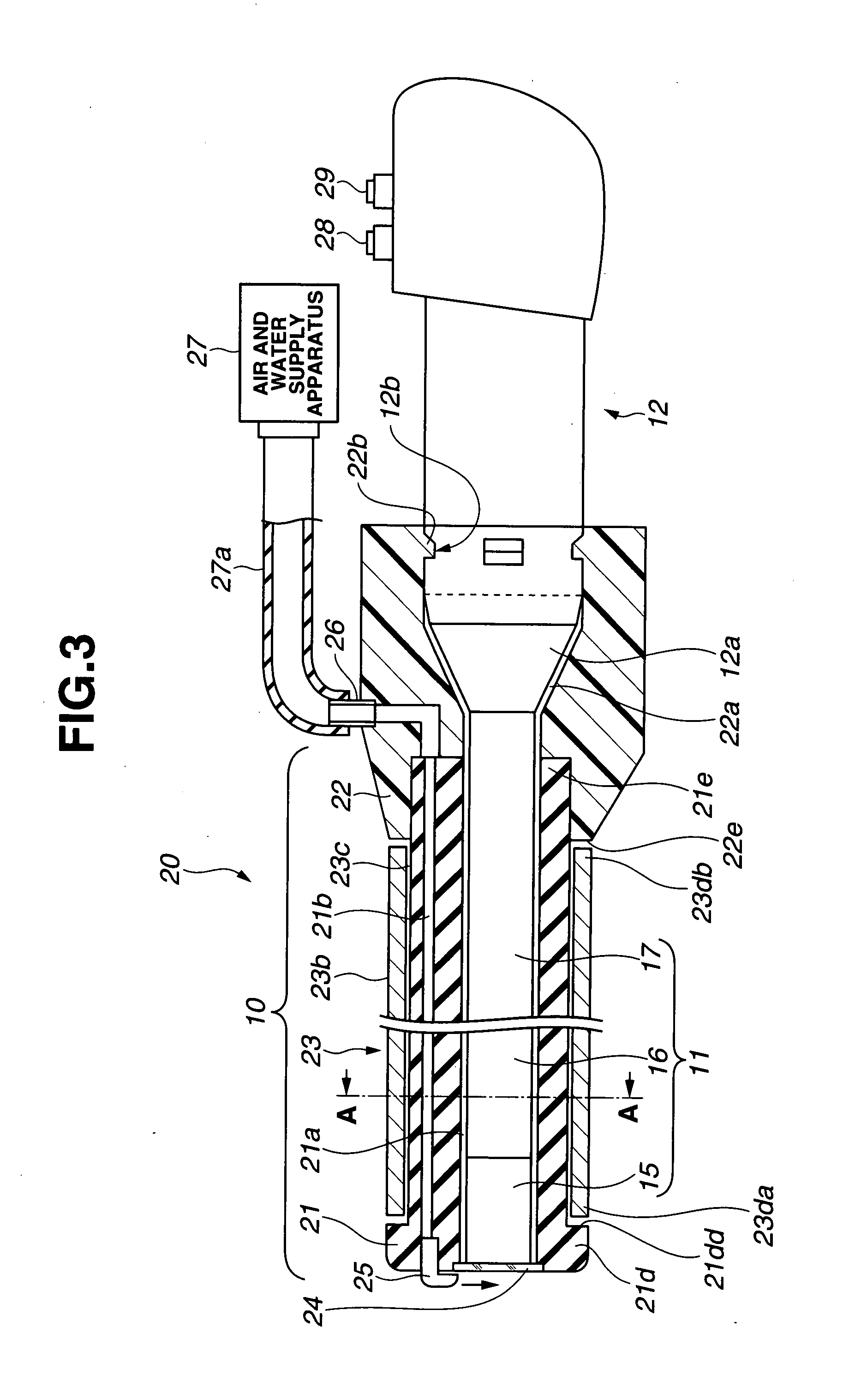
[0048]FIGS. 1 to 12 relate to a first embodiment according to the present invention. FIG. 1 is a view showing an overall configuration of an endoscope system in a first embodiment, FIG. 2 is an external view showing the vicinity of a distal end portion of an introductory tube in FIG. 1, FIG. 3 is a descriptive view showing the introductory tube and an endoscope in FIG. 1, FIG. 4 is a sectional view taken on line A-A in FIG. 3, FIG. 5 is a descriptive view showing a configuration of a rotation mechanism portion, FIG. 6 is a descriptive view of a substantial part showing the vicinity of a distal end portion of an introductory tube in FIG. 2, FIG. 7 is a descriptive view showing such a state that the introductory tube inserted with an insertion portion is inserted from an anus, FIG. 8 is a descriptive view showing such a state that a distal end portion of the introductory tube inserted with an insertion portion is inserted up to the vicinity of a caecum portion, FIG. 9 is a descriptive...
second embodiment
[0148]FIGS. 13 to 15 relate to a second embodiment according to the present invention. FIG. 13 is a descriptive view of a substantial part showing the vicinity of a distal end portion of an introductory tube configuring an endoscope system in a second embodiment, FIG. 14 is an enlarged view of a substantial part showing a first variant in FIG. 13 and FIG. 15 is an enlarged view of a substantial part showing a second variant in FIG. 13.
[0149]The first embodiment comprises ring members to be irregularities as a friction reduction section between an inner peripheral surface of the spiral tube 23 and the elastic cover tube 21 so as to reduce a contact resistance therebetween, while a second embodiment is configured so as to change the shape of the elastic cover tube 21 for obtaining irregularities as a friction reduction section. Other configurations are the same as in the first embodiment and descriptions thereof are omitted and the same configurations have the same symbols for descrip...
third embodiment
[0155]FIGS. 16 to 19 relate to a third embodiment according to the present invention. FIG. 16 is a descriptive view of a substantial part showing the vicinity of a distal end portion of an introductory tube configuring an endoscope system in a third embodiment, FIG. 17 is a descriptive view of a substantial part showing a first variant in FIG. 16, FIG. 18 is a descriptive view of a substantial part showing the vicinity of a distal end portion of an introductory tube of a second variant in FIG. 16 and FIG. 19 is a sectional view of the substantial part in FIG. 18.
[0156]The first embodiment comprises ring members to be irregularities as a friction reduction section between the inner peripheral surface of the spiral tube 23 and the outer peripheral surface of the elastic cover tube 21 so as to reduce a contact resistance therebetween, while a third embodiment is configured so as to provide winding portions at the elastic cover tube 21 for obtaining irregularities as a friction reductio...
PUM
 Abstract
Description
Claims
Application Information