
Electrical power supply device for endoscope and endoscope

a technology of endoscope and power supply device, which is applied in the field of endoscope and endoscope, can solve the problems of reducing the quality or subject image, affecting the operation of endoscope, so as to reduce the diameter of the insertion portion of the scope, reduce noise, and effectively utilize the effect of illuminating ligh

Inactive Publication Date: 2009-01-29
HOYA CORP
View PDF7 Cites 41 Cited by
  • Summary
  • Abstract
  • Description
  • Claims
  • Application Information

AI Technical Summary

Benefits of technology

[0008]Therefore, an objective of the present invention is to provide an electrical power supply device for an endoscope, that eliminates noise, reduces the diameter of the insertion portion of a scope, and allows the effective utilization of the illuminating light.

Problems solved by technology

As a result, the quality or a subject image may be degraded, or the imaging device may malfunction.
On the other hand, in an electronic endoscope where a part of the illuminating light for illuminating a subject is used unaltered as a power source, some useful illuminating light is lost and it is impossible to effectively use all the illuminating light emitted from a light source for observing a subject.

Method used


Image

  • Electrical power supply device for endoscope and endoscope
  • Electrical power supply device for endoscope and endoscope
  • Electrical power supply device for endoscope and endoscope

Examples


first embodiment

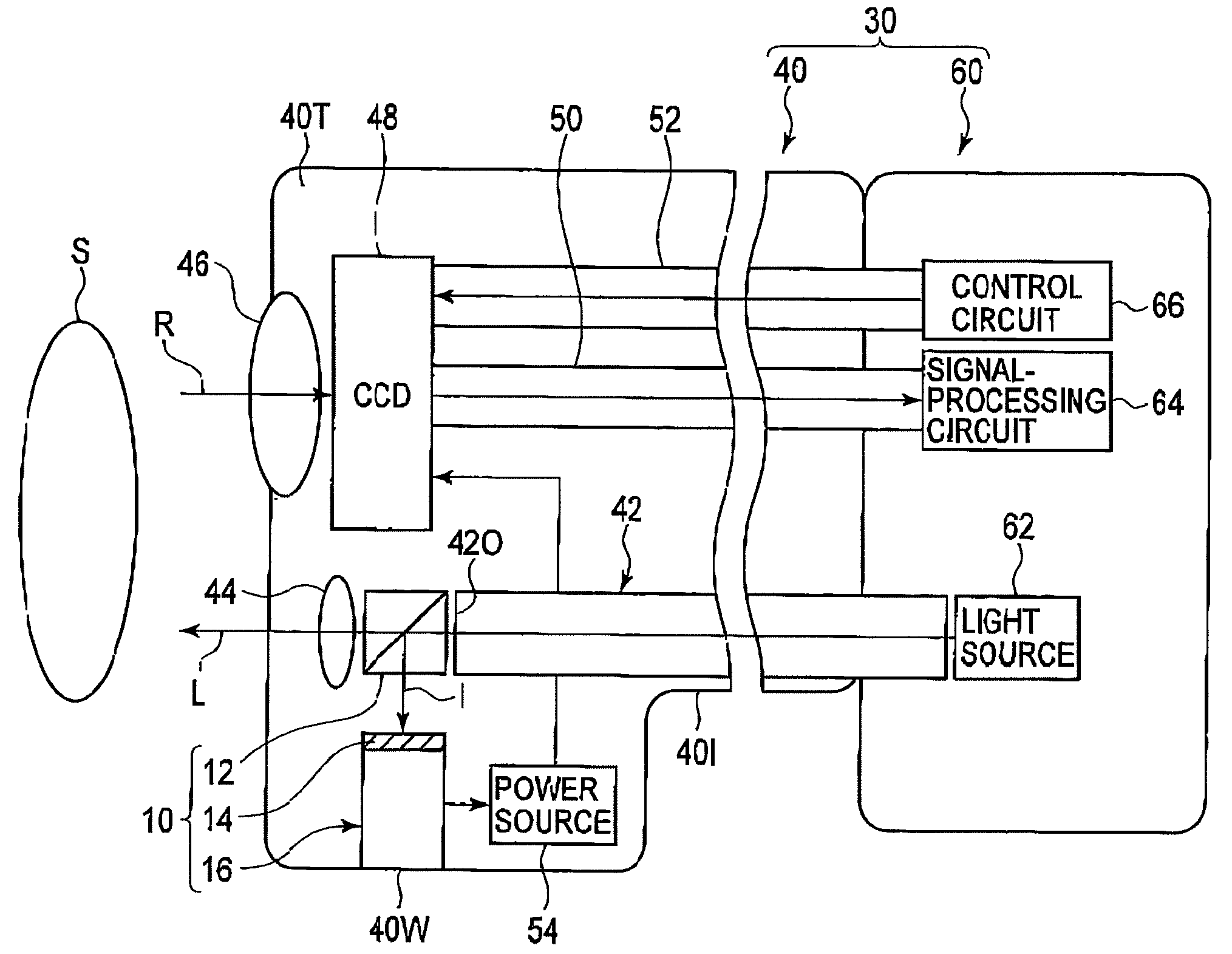
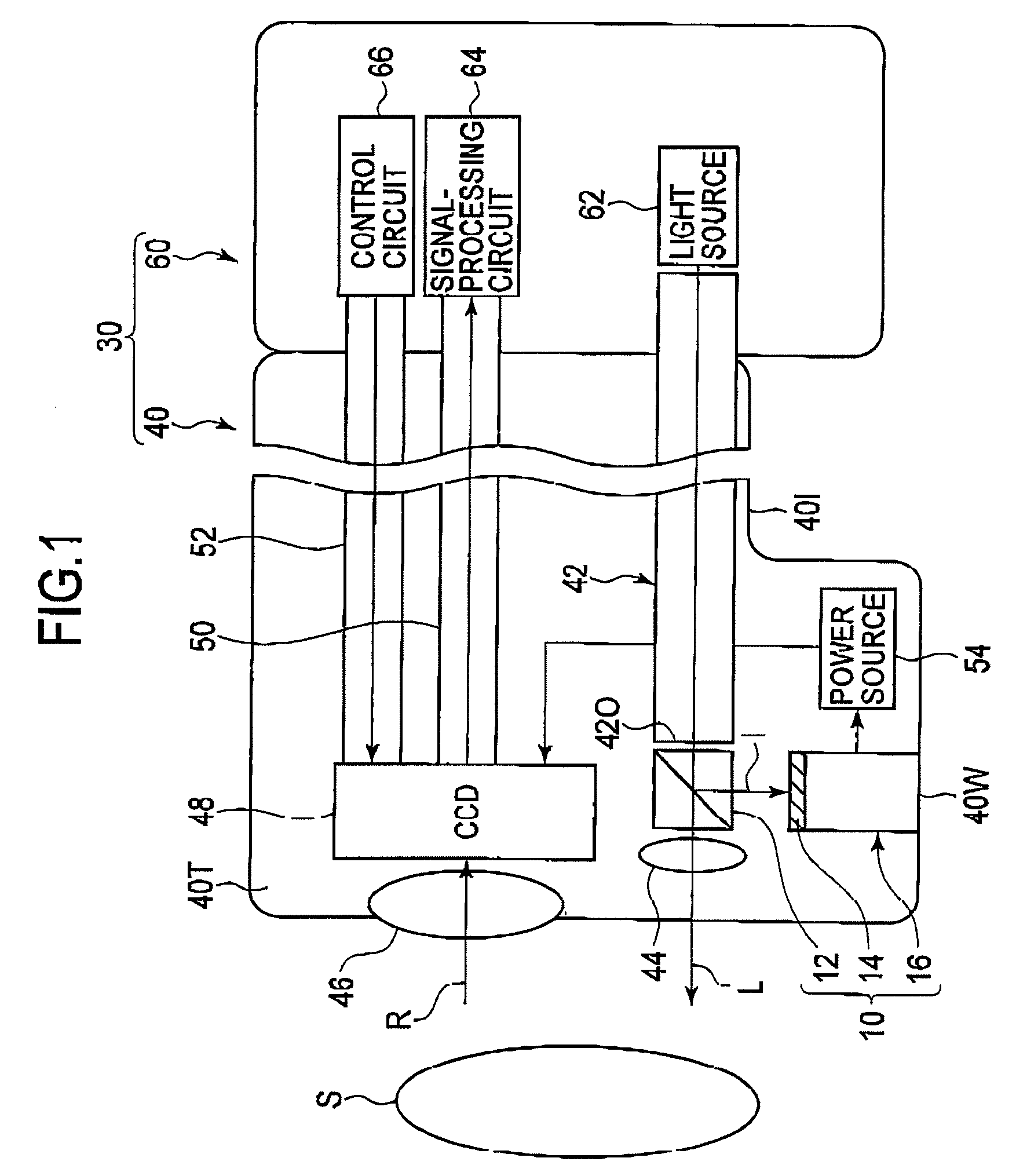
[0038]In the first embodiment, as explained above, electricity is supplied to components such as the CCD 48 in the tip 40T without the use of a power line, so that noise generation caused by the power line can be prevented. Furthermore, although the electrical power supply device 10 should be provided in the tip 40T, the diameter of the insertion portion 40I of the scope 40 for insertion into the body can be reduced, because a power line is not necessary. In addition, all the visible light components can be used for illuminating and photographing the subject S, so that the illuminating light emitted by the light source 62 can be effectively utilized.

[0039]Note that electricity generated by the electrical power supply device 10 may not only be used to drive the CCD 48, but also other components such as another circuit in a part provided in the tip 40T. This electrical power supply is applied to the following embodiments as well as the first embodiment.

[0040]Next, the second embodimen...

fourth embodiment

[0045]As explained above, in the fourth embodiment, the secondary battery 20 can be charged using the external power source 58 before the electronic endoscope 30 is used, that is, during the period when the insertion portion 40I of the scope 40 is not inserted into the body of the subject. Accordingly, the CCD 48 and other components can reliably begin functioning even when the emission of the illuminating light L by the light source 62 and electricity generation by the peltier device 16 have only just started, at the starting time of the electronic endoscope 30.

[0046]Furthermore, during an operation by a user, the electricity generated by the peltier device 16 can be used as well as the above-explained embodiments. Therefore, although the secondary battery 20 can not be charged by the external power source 58 during operation, observing and photographing the subject S can be carried out without any problem.

[0047]Next, the fifth embodiment is explained with reference to FIG. 5. In t...


PUM


Abstract

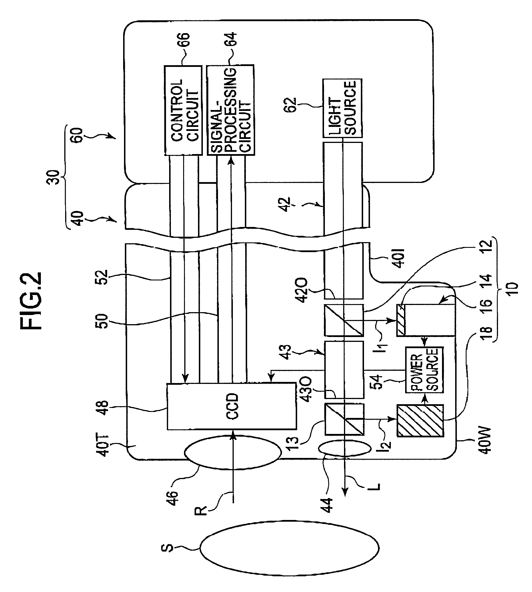
An electrical power supply device is for an endoscope having a scope for insertion into the body of a subject. The electrical power supply device includes a temperature controller and a thermoelectric converter. The thermoelectric converter controls the temperature of the interior of the scope. The thermoelectric converter generates electricity based on the difference in temperature between the body interior of the subject and the interior of the scope.

Description

BACKGROUND OF THE INVENTION[0001]1. Field of the Invention[0002]The present invention relates to an electrical power supply device for an endoscope, and an endoscope.[0003]2. Description of the Related Art[0004]Usually, an electronic endoscope has a scope including an imaging device and a processor that processes image signals generated by the imaging device. Known endoscopes include one in which electrical power is supplied via a power line from a power circuit provided in a processor to an imaging device in a scope, or another one in which electromagnetic coupling is used for electrical power supply to an imaging device instead of using the power line.[0005]Furthermore, there is also known an electronic endoscope containing in the scope, a solar cell which supplies electrical energy to an imaging device using part of the light for illuminating a subject.[0006]When a power line is connected to a scope, the power line may act as an antenna that transmits or receives external noise. ...

Claims


Application Information

Patent Timeline
Patent Type & Authority Applications(United States)
IPC IPC(8): A61B1/12A61B1/06
CPCA61B1/00029A61B1/00034A61B1/0008A61B1/128A61B1/05A61B2560/0214A61B1/00096
Inventor MINAKUCHI, TADASHI
Owner HOYA CORP
Learn More