Multistage Exhaust Turbocharger

Active Publication Date: 2009-02-05
MITSUBISHI HEAVY IND ENGINE & TURBOCHARGER LTD
View PDF16 Cites 30 Cited by
  • Summary
  • Abstract
  • Description
  • Claims
  • Application Information

AI Technical Summary

Benefits of technology

[0018]The present invention was made in light of the problems in conventional art, and the object is to provide a multistage exhaust turbocharger which is simplified in constr

Problems solved by technology

A comparatively large installation space is required in the engine room to install an engine equipped with a two-stage exhaust turbocharger of this type because it is inevitably increased in bulk as compared with a single-stage one.
However, in engines equipped with a two-stage exhaust turbocharger disclosed in U.S. Pat. No. 6,378,308 B1 and JP 59-82526, particularly an air supply path from a low-pressure compressor 2b to a high-pressure compressor 1b and an air supply bypass path from the low pressure compressor 2b to a compressor bypass valve device 5 on a high-pressure compressor bypass pipe 111 are arranged in

Method used


Image

  • Multistage Exhaust Turbocharger
  • Multistage Exhaust Turbocharger
  • Multistage Exhaust Turbocharger

Examples


Example

THE FIRST EMBODIMENT

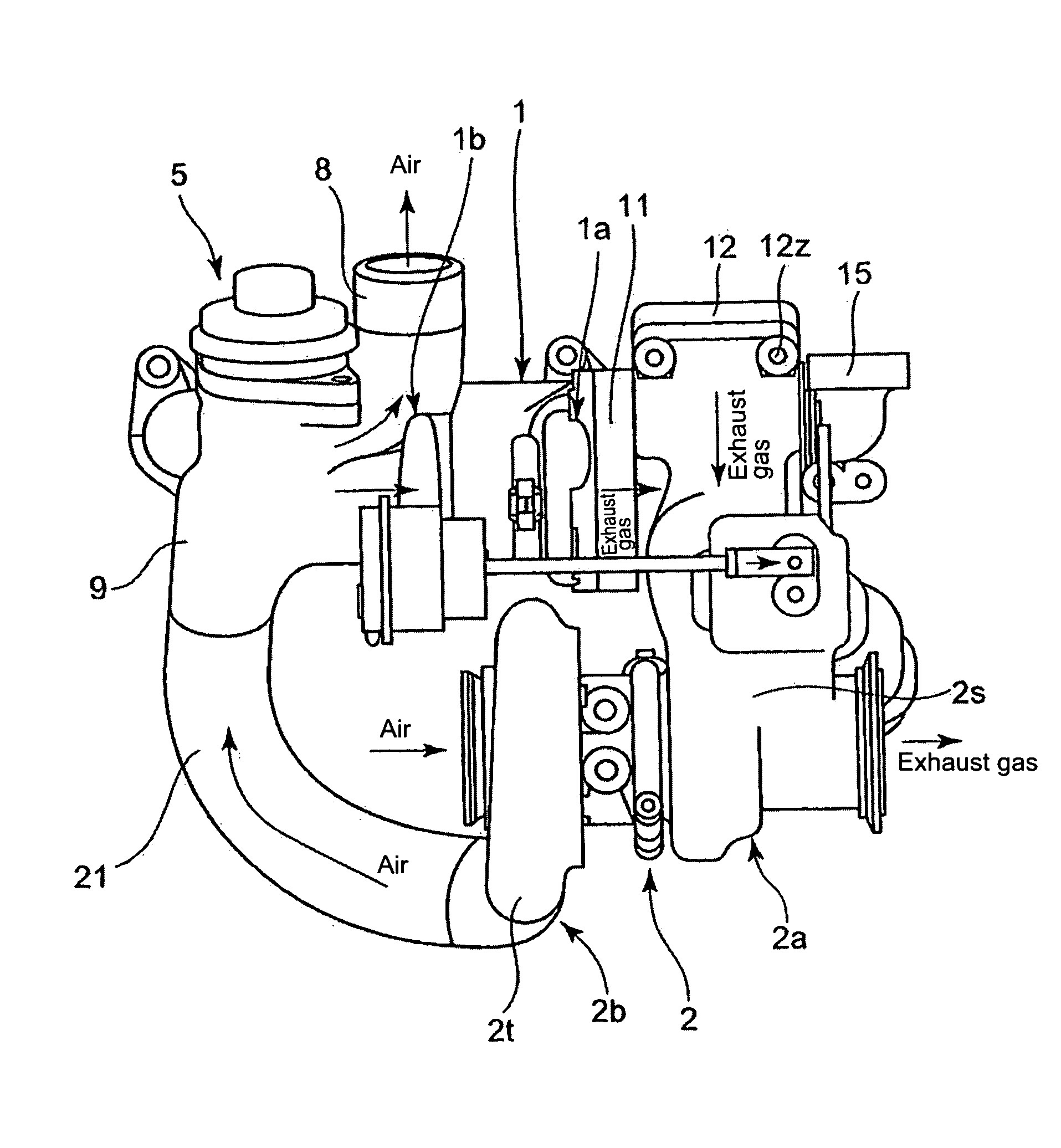
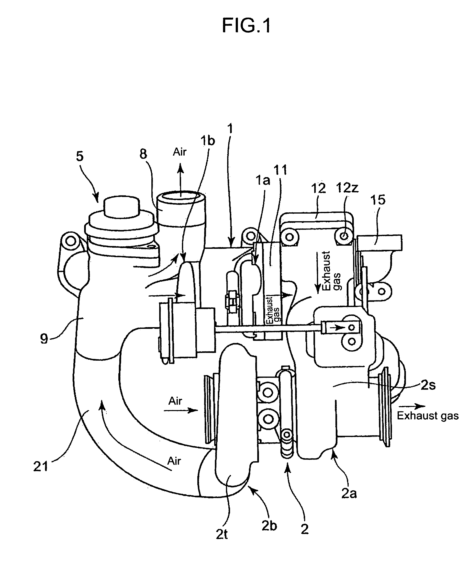
[0063]FIG. 1 is aside elevation showing the total construction of the first embodiment of the two-stage exhaust turbocharger according to the invention, FIG. 2 is a sectional view of the first embodiment of FIG. 1 along the center line of the rotor shaft of the high-pressure stage turbocharger, FIG. 3A is a perspective external view of the high-pressure compressor cover provided with the compressor bypass valve device, FIG. 3B is an external view of the compressor bypass valve device, and FIG. 4 is a sectional view of the high-pressure compressor cover.

[0064]Referring to FIGS. 1 to 4, reference numeral 1 is a high-pressure stage turbocharger having a high-pressure turbine 1a and a high-pressure compressor 1b connected to the turbine 1a by a shaft 3 (see FIG. 8), 2 is a low-pressure stage turbocharger having a low-pressure turbine 2a and a low-pressure compressor 2b connected to the turbine 2a by a shaft 4 (see FIG. 8).

[0065]Reference numeral 10 is a high-pressure...

Example

THE SECOND EMBODIMENT

[0077]FIG. 6A is a side elevation showing the turbine housing of the high-pressure stage exhaust turbocharger in the second embodiment of the invention, and FIG. 6B is a view in the direction of arrow Y in FIG. 6A. FIG. 7 is a view in the direction of arrow W in FIG. 6A.

[0078]Referring to FIGS. 6˜7, reference numeral 103 is an exhaust manifold, which is formed integral with the high-pressure turbine housing 10 of the high-pressure stage turbocharger 1 and made by metal casting. The exhaust gas guide member 11 is connected to the flange face 10a of an exhaust gas exit side the flange 10b of the high-pressure turbine housing 10 by a plurality of bolts not shown in the drawings with the longitudinal center line of the exhaust gas guide member 11 coinciding the rotation axis M of the high-pressure turbine 1a.

[0079]Reference numeral 103a is a flange of the exhaust manifold 103. The flange face 103b of each flange 103a is perpendicular to the flange face 10a of the f...


PUM


Abstract

An engine equipped with a multistage exhaust turbocharger easily mountable in a narrow engine room of a vehicle is provided by simplifying in construction and reducing in bulk of the multistage exhaust turbocharger. The multistage exhaust turbocharger has a high-pressure stage turbocharger and a low-pressure stage turbocharger. A high-pressure compressor cover of the high-pressure stage turbocharger is composed such that it has a compressor inlet passage, a bypass inlet passage, a switching aperture between both the passages to be opened and closed by a valve body of the compressor bypass valve device, and a bypass outlet pipe part connecting to the bypass inlet passage to introduce bypass air passed through the aperture opened by the bypass valve to the compressor bypass channel which is to be connected to the bypass outlet pipe part. A high-pressure turbine housing is cast integral with the exhaust manifold, an exhaust gas guide member is attached to the high-pressure turbine housing, and a low-pressure turbine housing is attached to the exhaust gas guide member.

Description

TECHNICAL FIELD[0001]The present invention relates to a multistage exhaust turbocharger for an internal combustion engine, the turbocharger comprising a high-pressure stage turbocharger having a high-pressure turbine drivable by exhaust gas from the engine and a low-pressure stage turbocharger having a low-pressure turbine drivable by exhaust gas from the high-pressure turbine, the turbochargers being arranged sequentially in the flow path of the exhaust gas, and supply air for the engine pressurized by a low-pressure compressor of the low-pressure stage turbocharger being supplied via an air supply channel to a high-pressure compressor of the high-pressure stage turbocharger to be further pressurized by the high-pressure compressor.BACKGROUND ART[0002]In recent years, in the field of on-vehicle engines, particularly on-vehicle diesel engines, multistage (two-stage) exhaust turbo-charging system is adopted, in which a high-pressure stage turbocharger having a high-pressure turbine d...

Claims


Application Information

Patent Timeline
IPC IPC(8): F02B37/16F02B33/34F02B37/013
CPCF02B37/013F02B37/16F02B37/004F01N13/10Y02T10/144F04D17/14F04D29/4213F05D2220/40Y02T10/12Y10T137/7898Y10T137/87812F02B37/12F02B39/00F02B39/02
Inventor AN, BYEONGILSHIRAISHI, TAKASHIKIKUCHI, TORUWAKITA, MAMORU
Owner MITSUBISHI HEAVY IND ENGINE & TURBOCHARGER LTD
Why Eureka
Try Eureka