

Refrigeration System
a technology of refrigerating system and air conditioner, which is applied in the direction of defrosting, domestic cooling apparatus, application, etc., can solve the problems of air adhesion and moisture, and achieve the effect of effective defrosting, and reducing the time taken to defros
- Summary
- Abstract
- Description
- Claims
- Application Information
AI Technical Summary
Benefits of technology
Problems solved by technology
Method used
Image

Examples
embodiment 1
Effects of Embodiment 1
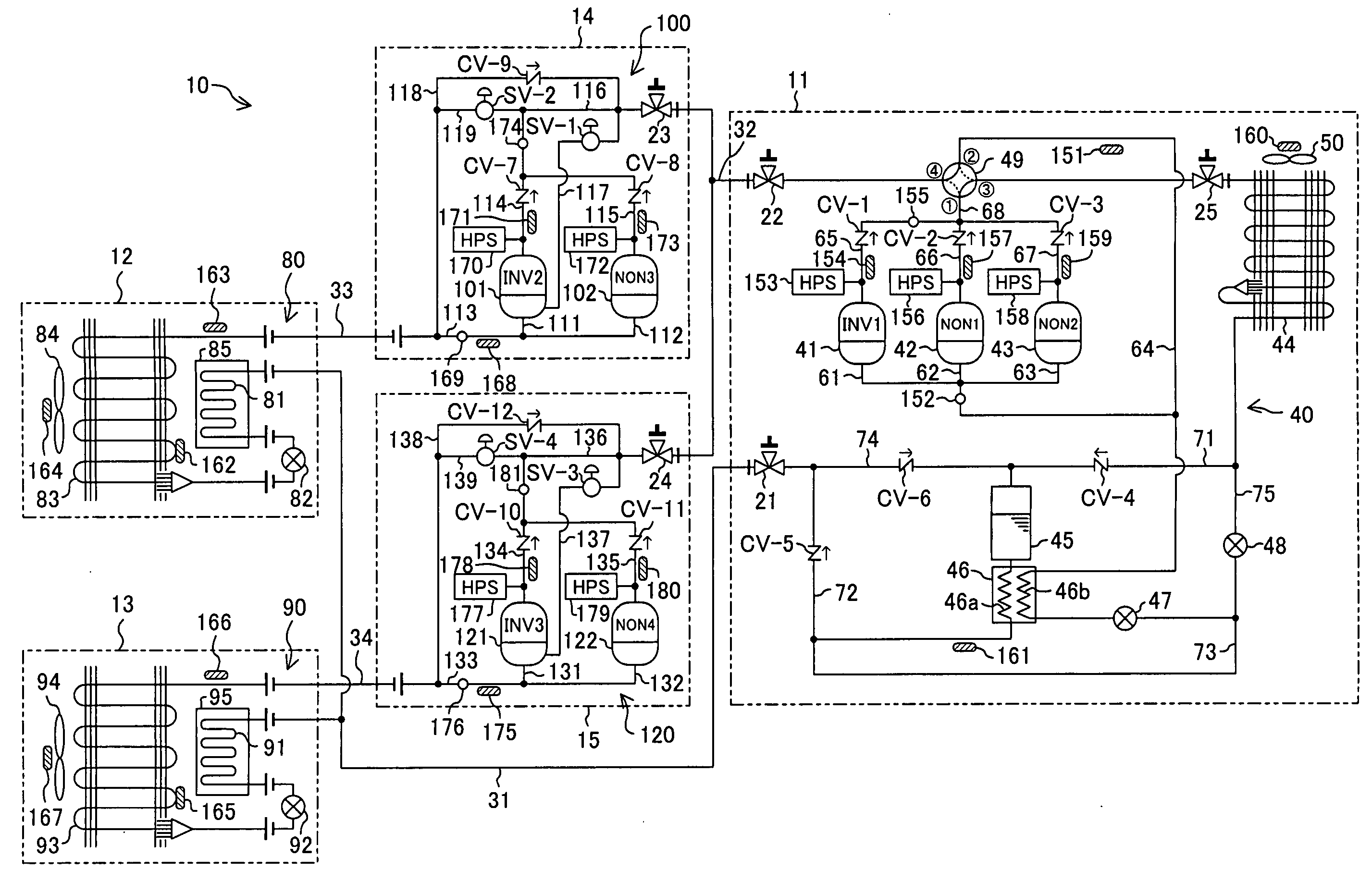
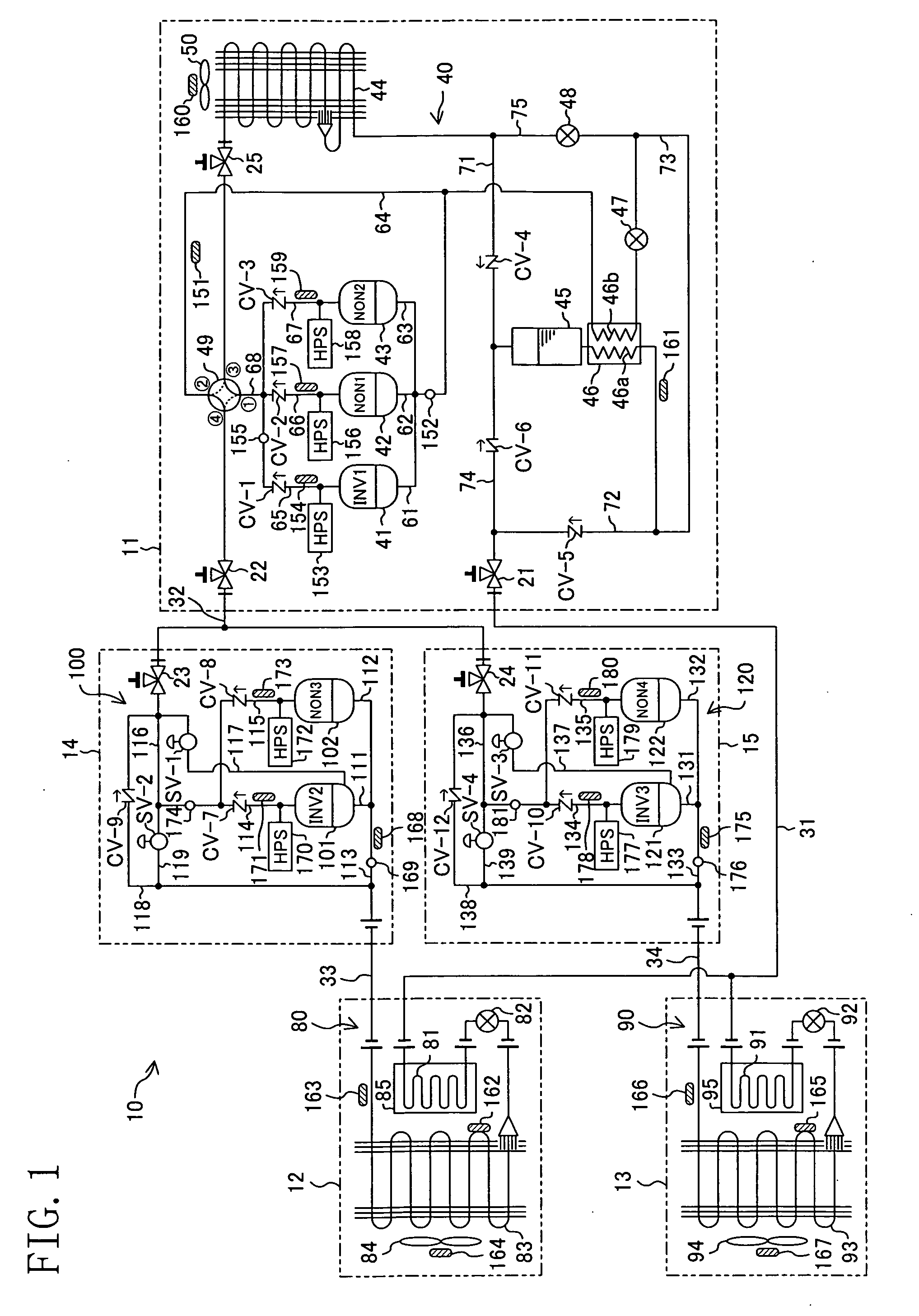
[0142]According to Embodiment 1, during the defrosting operation, frost adhering to the surfaces of the cooling heat exchangers (83, 93) are heated from the insides of the cooling heat exchangers (83, 93) by feeding the refrigerant discharged by the high stage compressors (41, 42, 43) into the utilization side heat exchangers (83, 93). Therefore, the cooling heat exchangers (83, 93) can be effectively defrosted, which reduces the time taken to defrost them.
[0143]Furthermore, according to Embodiment 1, since during the defrosting operation the outdoor heat exchanger (44) serves as an evaporator, heat given from air to refrigerant is used to defrost the utilization side heat exchangers (83, 93). In other words, according to Embodiment 1, heat given to refrigerant by the high stage compressors (41, 42, 43) and heat given to refrigerant by the outdoor heat exchanger (44) are both used to defrost the cooling heat exchangers (83, 93). This reduces the time required ...
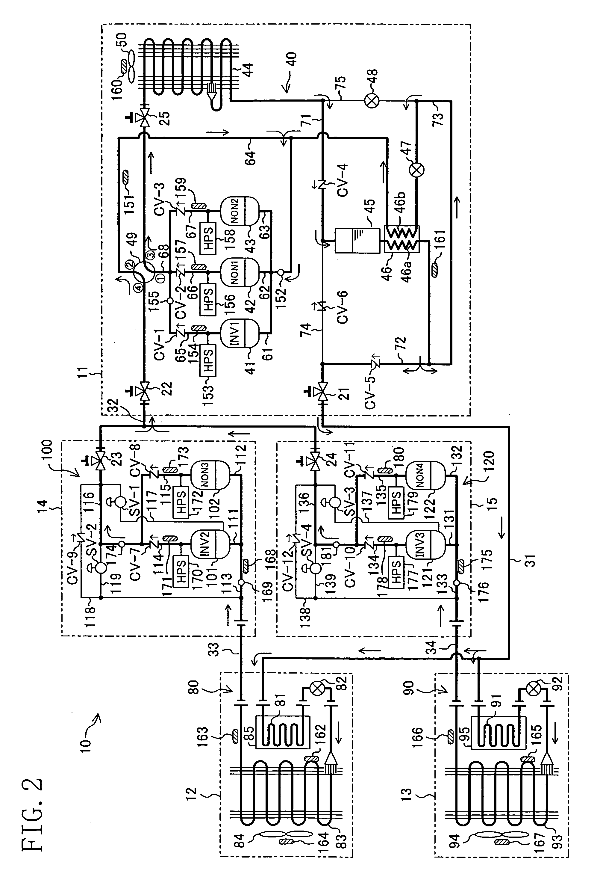
embodiment 2
Effects of Embodiment 2
[0163]According to Embodiment 2, like Embodiment 1, during the defrosting operation, frost adhering to the surfaces of the cooling heat exchangers (83, 93) are heated from the insides of the cooling heat exchangers (83, 93) by feeding the refrigerant discharged by the high stage compressors (41, 42, 43) into the cooling heat exchangers (83, 93). Therefore, the cooling heat exchangers (83, 93) can be effectively defrosted, which reduces the time taken to defrost them.
[0164]Furthermore, in Embodiment 2, the refrigeration system (10) can selectively perform the first defrosting operation and the second defrosting operation. According to Embodiment 2, when during the first defrosting operation the refrigeration system (10) is lacking in the capacity to defrost the cooling heat exchangers (83, 93), the low stage compressors (101, 102, 121, 122) are also driven. Therefore, according to Embodiment 2, the amount of heat given to refrigerant can be increased by the sec...
embodiment 3
Modifications of Embodiment 3
[0214]The oil separators (143, 144) and the oil return pipes (141, 142) described in Embodiment 3 may be applied to the refrigeration systems (10) of Embodiments 1 and 2 so that the refrigeration systems (10) can perform a similar cooling operation, a similar defrosting operation and a similar refrigerant recovery action to those in Embodiment 3. Furthermore, for example, in the booster circuits (100, 120) in Embodiment 3 shown in FIG. 9, the bypass pipes (119, 139) may be connected at their one ends to the discharge connection pipes (116b, 136b), respectively, and connected at the other ends to the low stage suction pipes (113, 133), respectively. According to this configuration, during the defrosting operation, the cooling heat exchangers (83, 93) can be defrosted, without sending high-pressure refrigerant into the oil separators (143, 144), by directly introducing it into the bypass pipes (119, 139).
[0215]Furthermore, for example, as shown in FIG. 11,...
PUM
 Abstract
Description
Claims
Application Information