Implement/vehicle steering control system and method

a technology for steering control and implements, applied in the direction of tractor steering, agriculture tools and machines, adjusting devices, etc., can solve the problems of correspondingly long time, inability to address individual problems, and the installation of a correspondingly heavy front weight on the tractor, so as to avoid the free movement of the steerable wheel of the implemen

Inactive Publication Date: 2009-02-05
DEERE & CO
View PDF28 Cites 63 Cited by
  • Summary
  • Abstract
  • Description
  • Claims
  • Application Information

AI Technical Summary

Benefits of technology

[0016]Quite preferably, the steering of the steerable wheel can be blocked if the utility vehicle is reversing. As a result, a situation in which the steerable wheel is deflected in the “incorrect” direction when reversing is avoided in all cases. Since the blocking of the wheel occurs quasi automatically as a function of the operating state—the engagement of the reverse gear or the reversing—of the utility vehicle or of the implement, it is also impossible for this to be forgotten by an operator of the utility vehicle and a critical situation therefore cannot arise due to inattentiveness of the operator.
[0017]According to one preferred embodiment, the steering of the steerable wheel can be blocked if the utility vehicle exceeds a predefined speed, such as, for example, 15 or 20 km / h since at such a speed it is possible to assume that the vehicle combination is on the road and in the operating state of travel. In this context, the vehicle combination is travelling at an increased speed and as a result a free and deflecting movement of steerable wheel of the implement is avoided.

Problems solved by technology

Usually, this process is carried out manually by the operator and takes a correspondingly long time.
However, this requires installing a correspondingly heavy front weight on the tractor.
However, it is then a component of a learnable sequence and generally cannot be addressed individually.
Furthermore, such actuation of the additional hydraulic valves is associated with time or travel.
Such trailing steering systems have, in particular when travelling quickly and on a slope a lack of straight ahead running properties if the steering of the wheels is not blocked.
Even when reversing, the trailing steering systems usually steer in the wrong direction.
Furthermore, the coupling of the implement to the linkage on a tractor is awkward.
Such positive steering systems restrict the maximum achievable drawbar angle so that the vehicle combination has in total a relatively large turning radius.
The hydraulic connection in positive steering systems is also more complex and therefore more expensive.

Method used


Image

  • Implement/vehicle steering control system and method
  • Implement/vehicle steering control system and method
  • Implement/vehicle steering control system and method

Examples


Embodiment Construction

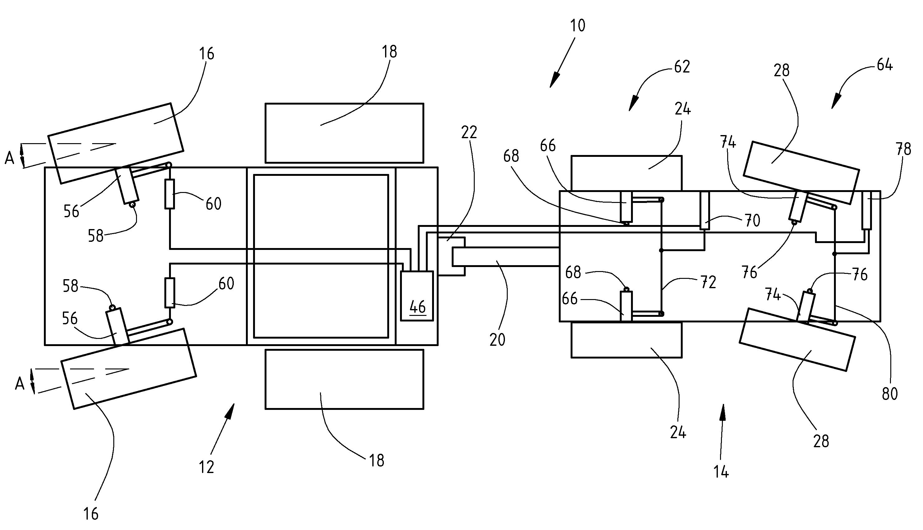
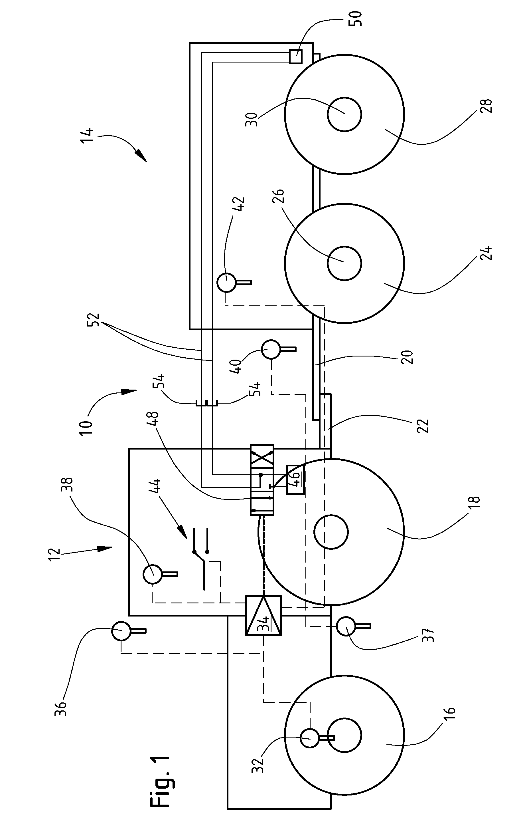
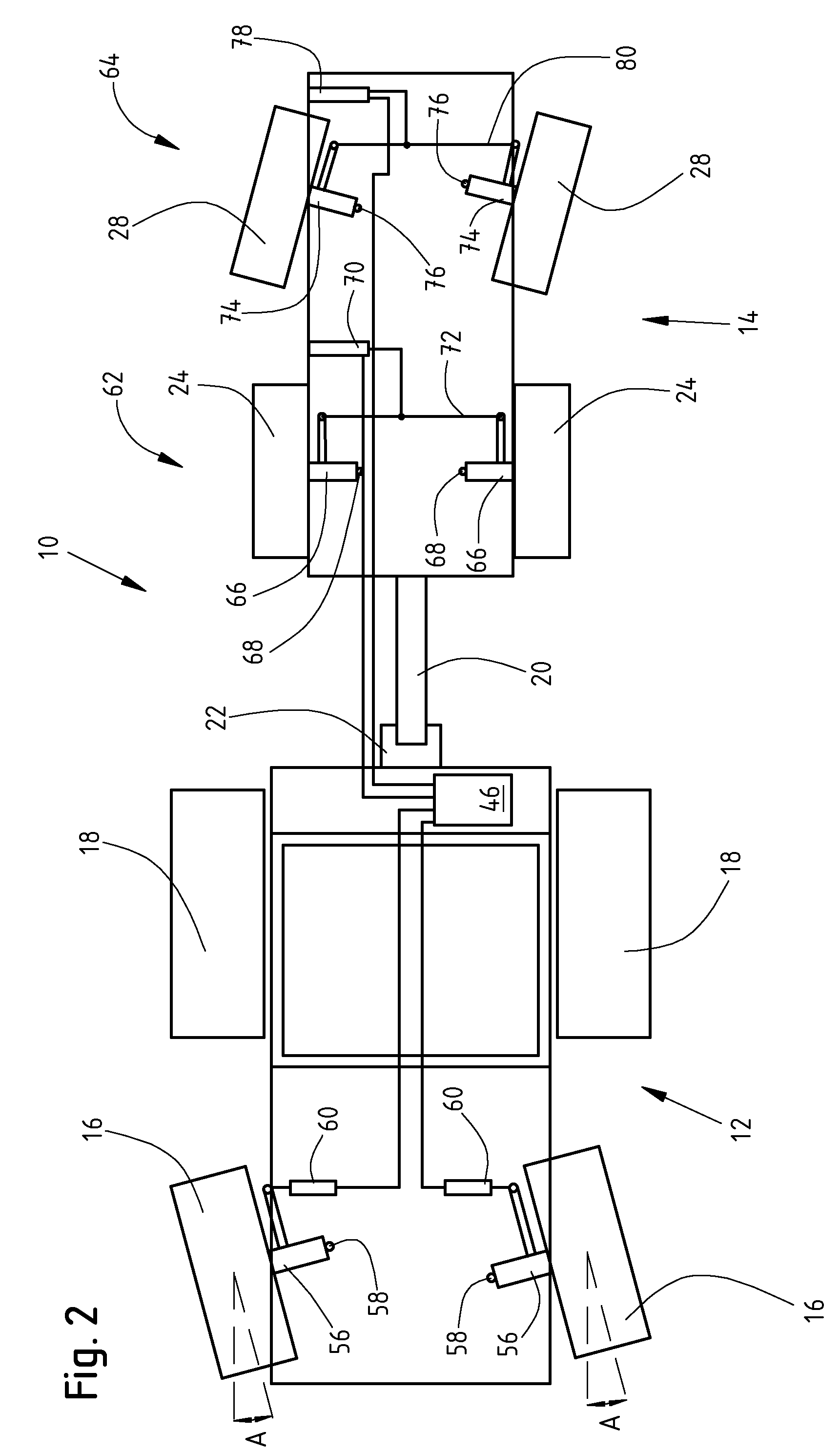
[0028]In FIG. 1, a vehicle combination 10 includes an agricultural utility vehicle 12, such as a tractor, and an implement 14. The implement 14 may be a towed trailer. The tractor 12 has two front wheels 16 and two rear wheels 18. The front wheels 16 are steerably coupled to an individual wheel suspension (not shown). The trailer 14 is coupled to a drawbar 12 at the drawbar hitch 22 of the tractor 12. The trailer 14 has front wheels 24 which are rotatably mounted on a front axle 26 which is non steerable. The rear wheels 28 of the trailer 14 are rotatably and steerably mounted on the trailing steering axle 30. The rear wheels 28 are coupled to an individual wheel suspension (not shown) on the chassis of the trailer 14. The implement (14) can be coupled to the utility vehicle by means of a drawbar jaw, a hitch (22), a ball coupling, a bayonet coupling, a three point equipment attachment or a hexapod.

[0029]The tractor 12 has a plurality of sensors. It is therefore possible, for exampl...


PUM


Abstract

A control system controls steering of an implement which is coupled to an agricultural utility vehicle. The control system includes a control unit, a sensor, a hydraulic system on the utility vehicle, an electronically actuatable hydraulic valve, a hydraulic actuator on the implement and a steerable wheel on the implement. A status variable of the utility vehicle or of the implement can be detected with the sensor and transmitted to the control unit. A current operating state of the utility vehicle and/or of the implement is determined by the control unit. The hydraulic valve is connected to the hydraulic system and to the actuator. The hydraulic valve can be actuated as a function of the current operating state of the utility vehicle and/or of the implement in order to block the steering of the wheel with the actuator.

Description

FIELD OF THE INVENTION [0001]The invention relates to a control system and a method for operating a control system for steering an implement which is coupled to an agricultural utility vehicle.BACKGROUND OF THE INVENTION [0002]Tractors include a hydraulic system which generally has a hydraulic pump driven by the internal combustion engine, a hydraulic reservoir and a plurality of further hydraulic components, such as valves, throttles and hydraulic actuators, by way of example. A tractor usually has additional hydraulic valves with which working functions of an implement which can be coupled to the tractor can be actuated. To this extent, working functions of the implement are supplied by the hydraulic system of the tractor. These additional valves are generally actuated electronically. Examples of working functions are lifting or lowering parts of equipment, wherein parts of equipment may be, in particular, furrow cutters, a sowing machine attached in semitrailer fashion to a soil ...

Claims


Application Information

Patent Timeline
Patent Type & Authority Applications(United States)
IPC IPC(8): A01B63/00
CPCA01B69/006B62D13/00A01B69/004B62D13/025B62D13/04B62D13/005
Inventor HAHN, KLAUS
Owner DEERE & CO
Why Eureka
Try Eureka