Electric bushing and a method of manufacturing an electric bushing
a technology of electric bushings and electric spherical wires, which is applied in the field of bushings, can solve the problems of gas/liquid leakage, difficulty in achieving satisfactory sealing, and sliding between the insulator body, and achieve the effect of effective sealing
- Summary
- Abstract
- Description
- Claims
- Application Information
AI Technical Summary
Benefits of technology
Problems solved by technology
Method used
Image

Examples
Embodiment Construction
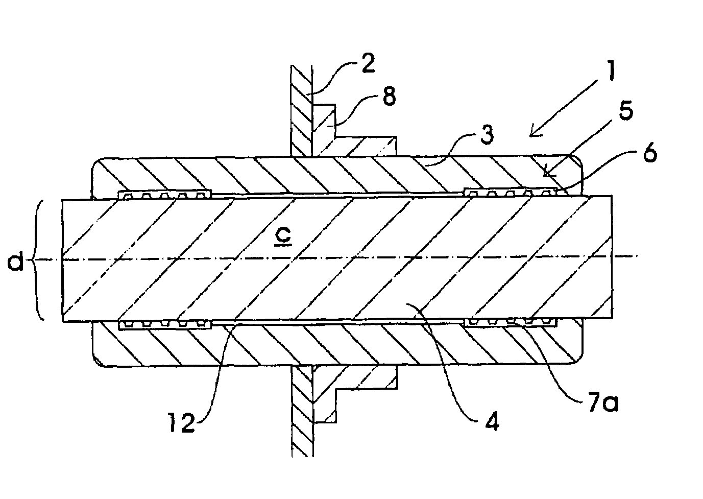
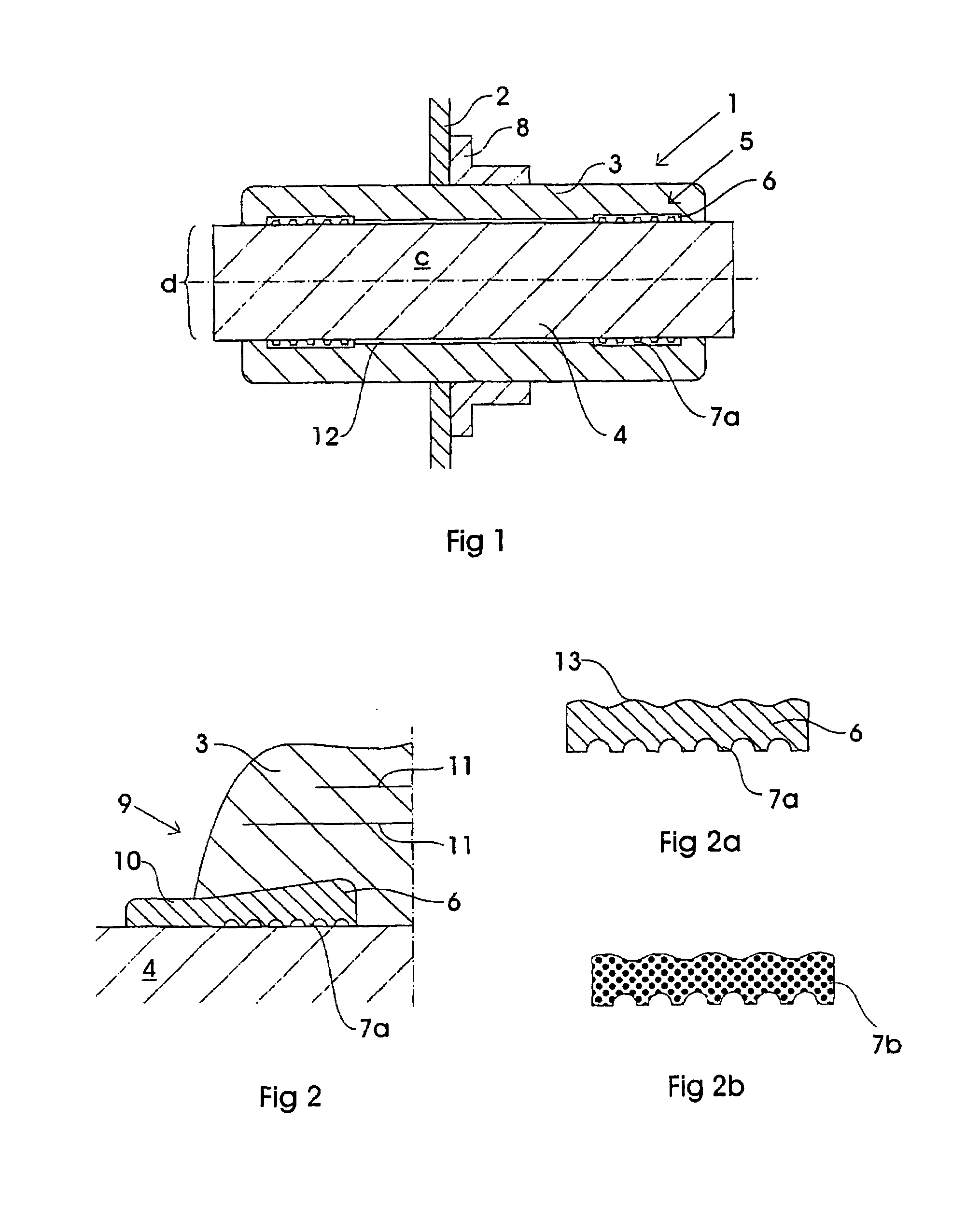
[0013]According to one preferred embodiment, the sealing element at the bushing is designed as an annular band where the compressible means comprise grooves facing the conductor. One advantage with the grooves is that they will also under compressed condition slide against the surface of the conductor, during temperature change at the conductor and the insulation body, and still keep its sealing ability.
[0014]According to one preferred embodiment, the compressible means of sealing element comprise gas-filled cavities. Such cavities improve the elasticity of the sealing member.
[0015]According to one preferred embodiment, the compressible means of sealing element comprise groves as well as gas-filled cavities.
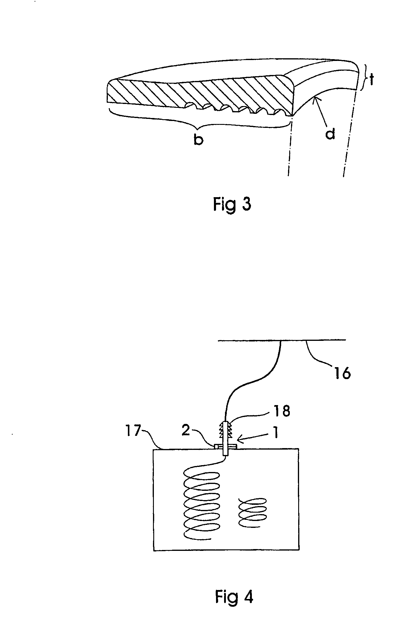
[0016]According to one embodiment, the sealing element is designed for geometric locking of the sealing element, for example in the form of locking grooves. The sealing element may alternatively exhibit a cross section with a thickness increasing in a direction towards the centre...
PUM
| Property | Measurement | Unit |
|---|---|---|
| outer diameter | aaaaa | aaaaa |
| outer diameter | aaaaa | aaaaa |
| width | aaaaa | aaaaa |
Abstract
Description
Claims
Application Information