Earth-boring tools having particle-matrix composite bodies, methods for welding particle-matrix composite bodies and methods for repairing particle-matrix composite bodies

a technology of composite materials and earth-boring tools, which is applied in the direction of furnaces, heat treatment equipment, soldering equipment, etc., can solve the problems of particle-matrix composite materials that cannot be welded alone, may not be able to withstand cutting stresses alone, and may be relative brittle and may not be able to withstand cutting stresses

Active Publication Date: 2009-02-05
BAKER HUGHES INC
View PDF33 Cites 42 Cited by
  • Summary
  • Abstract
  • Description
  • Claims
  • Application Information

AI Technical Summary

Problems solved by technology

For example, in the context of machine tool cutters, refractory carbide ceramic provides a relatively hard cutting surface but is relatively brittle and may not be able to withstand cutting stresses alone, whereas a metal may be too soft to provide a good cutting surface.
Although particle-matrix composite materials have many favorable material properties, one difficulty in the use of particle-matrix composite materials is that welding using localized heat, such as arc welding, may cause cracks to occur in particle-matrix composite materials.
These carbides are a few times greater in particle size than tungsten carbide and are very brittle, and can thus cause separation of the weld and cracking.
It has been observed however, that welding particle-matrix composite materials (for example a material comprising tungsten carbide particles in a cobalt matrix) to steel according to Shinozaki et al. may still result in cracking of the particle-matrix composite material proximate the weld.

Method used


Image

  • Earth-boring tools having particle-matrix composite bodies, methods for welding particle-matrix composite bodies and methods for repairing particle-matrix composite bodies
  • Earth-boring tools having particle-matrix composite bodies, methods for welding particle-matrix composite bodies and methods for repairing particle-matrix composite bodies
  • Earth-boring tools having particle-matrix composite bodies, methods for welding particle-matrix composite bodies and methods for repairing particle-matrix composite bodies

Examples


Embodiment Construction

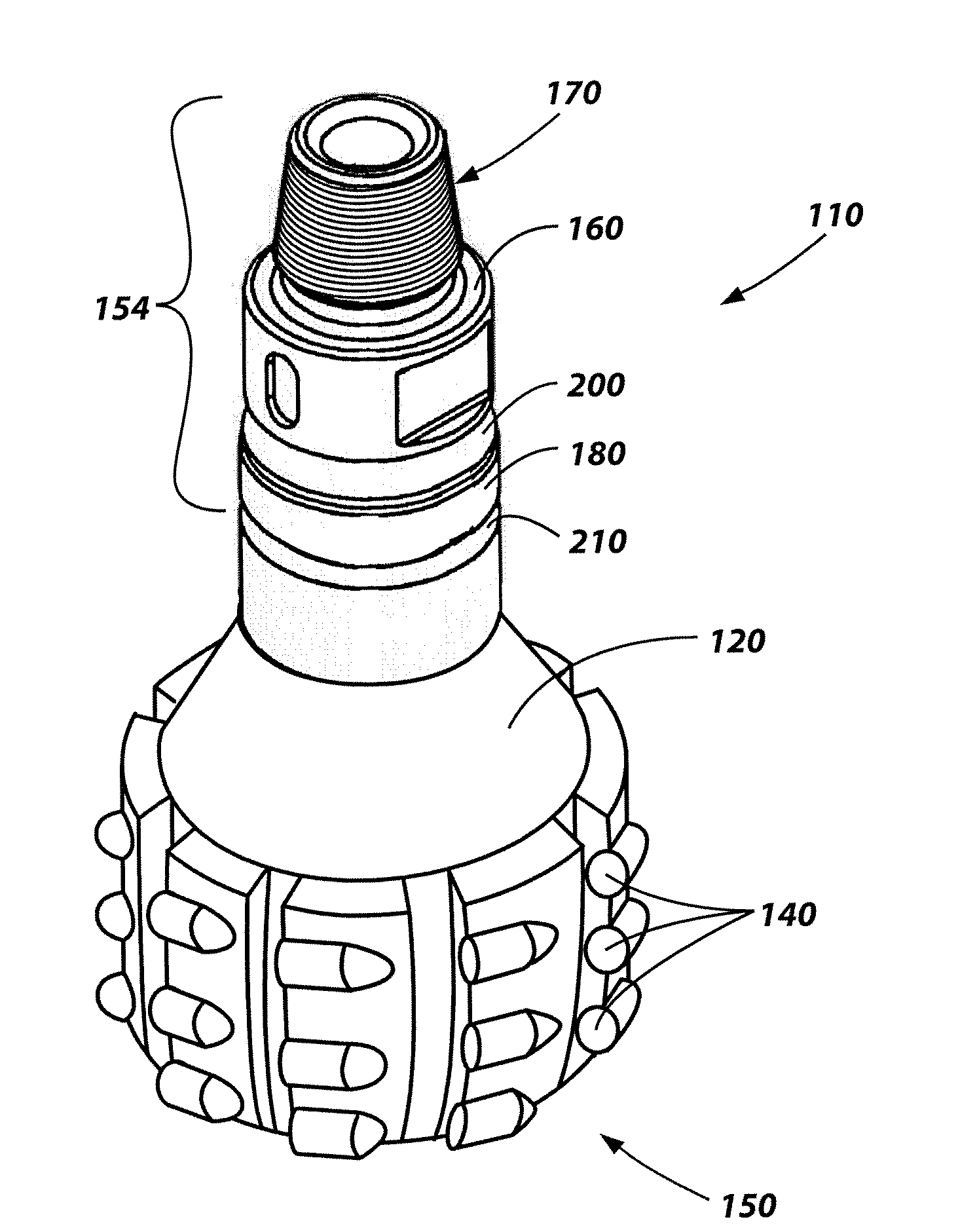
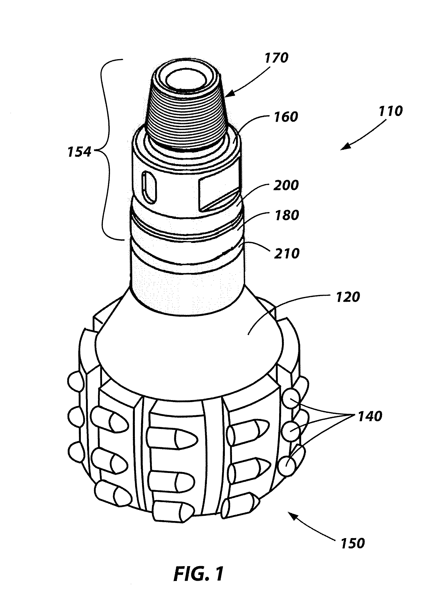
[0020]The depth of subterranean well bores being drilled continues to increase as the number of shallow depth hydrocarbon-bearing earth formations continues to decrease. These increasing well bore depths are pressing conventional drill bits to their limits in terms of performance and durability. Several drill bits are often required to drill a single well bore, and changing a drill bit on a drill string can be expensive in terms of drilling rig time due to the necessity to withdraw or “trip out” thousands of feet of drill pipe to replace a worn drill bit, replace it with a new one, and “trip in” the new drill bit to the bottom of the well bore to resume drilling.

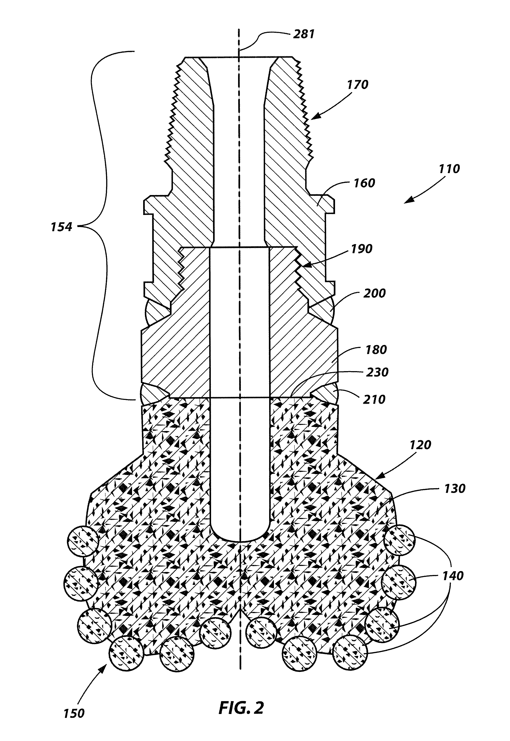
[0021]New particle-matrix composite materials are currently being investigated in an effort to improve the performance and durability of earth-boring rotary drill bits. Furthermore, bit bodies comprising at least some of these new particle-matrix composite materials may be formed from methods other than traditional infiltrat...


PUM

PropertyMeasurementUnit
temperatureaaaaaaaaaa

Abstract

Methods for welding a particle-matrix composite body to another body and repairing particle-matrix composite bodies are disclosed. Additionally, earth-boring tools having a joint that includes an overlapping root portion and a weld groove having a face portion with a first bevel portion and a second bevel portion are disclosed. In some embodiments, a particle-matrix bit body of an earth-boring tool may be repaired by removing a damaged portion, heating the particle-matrix composite bit body, and forming a built-up metallic structure thereon. In other embodiments, a particle-matrix composite body may be welded to a metallic body by forming a joint, heating the particle-matrix composite body, melting a metallic filler material forming a weld bead and cooling the welded particle-matrix composite body, metallic filler material and metallic body at a controlled rate.

Description

RELATED APPLICATIONS[0001]This application is a continuation-in-part of U.S. patent application Ser. No. 11 / 833,510 entitled METHODS AND SYSTEMS FOR WELDING PARTICLE-MATRIX COMPOSITE BODIES filed Aug. 3, 2007, the entire disclosure of which is hereby incorporated by reference.FIELD[0002]The invention relates generally to methods of welding materials susceptible to thermal shock, and to devices resulting from such welding. More particularly, embodiments of the invention relate to methods for welding a particle-matrix composite body to another body. Embodiments of the invention also relate to methods for repairing a particle-matrix composite body of an earth-boring tool. Additional embodiments of the invention include earth-boring tools having a joint between a particle-matrix composite body and a metallic body.BACKGROUND[0003]Particle-matrix composite materials may be composed of particles embedded in a matrix. For example, relatively hard particles of a carbide ceramic such as tungs...

Claims


Application Information

Patent Timeline
Patent Type & Authority Applications(United States)
IPC IPC(8): E21B10/62C21D1/34
CPCB23K9/0282B23K35/24B23K9/232B23K9/235B23K26/285B23K26/421B23K2201/002B23K2203/18B23K26/328B23K26/345B23K26/3206B23K26/34C21D9/50B23K35/3046B23K35/3053B23K35/3066B23K35/327B23K35/3601B23K35/0244B23K9/044B23K26/32B23K26/342B23K26/282B23K26/60B23K2101/002B23K2103/16B23K2103/18B23K2103/50
Inventor STEVENS, JOHN H.SMITH, REDD H.OXFORD, JAMES A.RAMIREZ, JOSE E.AMES, NATHAN D.KHURANA, SHUCHI P.
Owner BAKER HUGHES INC
Why Eureka
Try Eureka