
Color job reprint set-up for a printing system

a printing system and color job technology, applied in the direction of digital output to print units, digitally marking record carriers, instruments, etc., can solve the problems of color consistency and color matching that can aris

Inactive Publication Date: 2009-02-05
XEROX CORP
View PDF6 Cites 21 Cited by
  • Summary
  • Abstract
  • Description
  • Claims
  • Application Information

AI Technical Summary

Benefits of technology

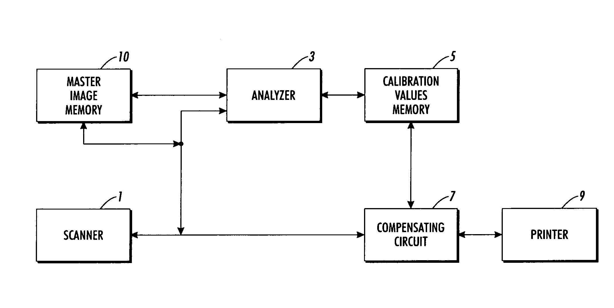
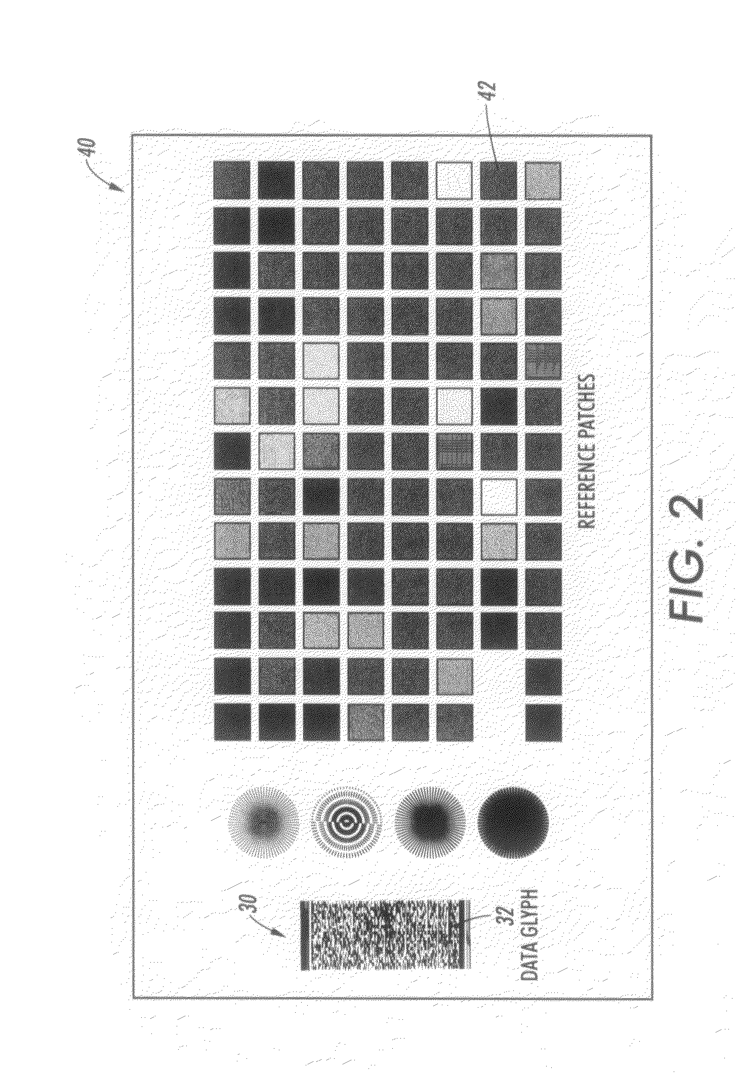
[0123]A printing system is provided for enabling a consistent color job re-print comprising a plurality of image marking engines. The system includes printing a master test image document printed by at least a first image marking engine. The master test image can have a data glyph and a plurality of reference patches. The data glyph can record distinct job attributes and the plurality of reference patches can record color parameters of a desired output. The system further provides a scanner for scanning the master test image document. The data glyph can provide the job attributes of the master test image document and can generate set-up data therefrom. The reference patches can provide the color parameters of the master test image document and can generate set-up data therefrom. The data glyph and the reference patches of the scanned image data are compared with retrieved prestored image data for generating compensation values based on a difference between the scanned image set-up data and the prestored image data for at least a first subsequent image document on the same first image marking engine or a second image marking engine.

Problems solved by technology

In a color xerographic printing system that comprises multiple xerographic engines or image marking engines, a problem of color consistency and color matching can arise between individual image marking engines of an integrated system or between the same image marking engine from one print job relative to another subsequent print job.

Method used


Image

  • Color job reprint set-up for a printing system
  • Color job reprint set-up for a printing system
  • Color job reprint set-up for a printing system

Examples


Embodiment Construction

[0130]In many areas of copier / printer / scanner image quality testing, it is desirable to start with a known test or master, process it through the machine under test, and analyze the resulting image. Based on the results of this analysis, the machine under test, can be adjusted, calibrated, or compensated via various control points. For example, if a halftone pattern is being reproduced on a laser printer, the resulting reflectance of the electronically generated halftone can change from printer to printer or overtime for the same printer. If the output from a printer is digitized via a scanner, the printer's response to an applied halftone can be measured and compensated for by modifying parameters within the halftoning process such as the tonal reproduction curve. Thus, by applying a known input, and measuring the error between the desired output and the actual output, a matrix of correction terms can be derived to obtain the desired output from the machine.

[0131]FIG. 1 illustrates...


PUM


Abstract

A printing system is provided for enabling a consistent color job re-print comprising a plurality of image marking engines. The system includes printing a master test image document printed by at least a first image marking engine. The master test image can have a data glyph and a plurality of reference patches. The data glyph can record distinct job attributes and the plurality of reference patches can record color parameters of a desired output. The system further provides a scanner for scanning the master test image document. The data glyph can provide the job attributes of the master test image document and can generate set-up data therefrom. The reference patches can provide the color parameters of the master test image document and can generate set-up data therefrom.

Description

[0001]The following patents / applications, the disclosures of each being totally incorporated herein by reference are mentioned:[0002]U.S. Publication No. US-2006-0114497-A1 (Attorney Docket No. 20031830-US-NP), Published Jun. 1, 2006, entitled “PRINTING SYSTEM,” by David G. Anderson, et al., and claiming priority to U.S. Provisional Application Ser. No. 60 / 631,651, filed Nov. 30, 2004, entitled “TIGHTLY INTEGRATED PARALLEL PRINTING ARCHITECTURE MAKING USE OF COMBINED COLOR AND MONOCHROME ENGINES”;[0003]U.S. Publication No. US-2006-0067756-A1 (Attorney Docket No. 20031867Q-US-NP), filed Sep. 27, 2005, entitled “PRINTING SYSTEM,” by David G. Anderson, et al., and claiming priority to U.S. Provisional Patent Application Ser. No. 60 / 631,918 (Attorney Docket No. 20031867-US-PSP), filed Nov. 30, 2004, entitled “PRINTING SYSTEM WITH MULTIPLE OPERATIONS FOR FINAL APPEARANCE AND PERMANENCE,” and U.S. Provisional Patent Application Ser. No. 60 / 631,921, filed Nov. 30, 2004, entitled “PRINTING ...

Claims


Application Information

Patent Timeline
IPC IPC(8): G06F3/12
CPCH04N1/60H04N1/6055
Inventor BRAY, DANIELBURRY, AARON M.
Owner XEROX CORP
Learn More