Head-up display system

a display system and head-up display technology, applied in the field of display systems, can solve the problems of increasing the cost of the head-up display system, affecting and complicated manufacturing of such structures, and achieve the effect of increasing the clearness of the projected text or image information

Active Publication Date: 2009-02-05
AURISE INVESTMENT CO LTD
View PDF6 Cites 51 Cited by
  • Summary
  • Abstract
  • Description
  • Claims
  • Application Information

AI Technical Summary

Benefits of technology

[0010]The frame demonstration medium can be designed to selectively pass or block the laser light, and thus increase the clearness of the projected text or image information. For example, a band pass optical film can only pass the visible light within the selected range of wave length and displays the virtual image corresponding to this wave length range. A polarization film can filter the laser light having the same polarization direction, and displays the virtual image corresponding to the polarization direction. In other words, the frame demonstration medium 106 is a polarization film for adjusting the reflection ratio of the visible light. It should be noticed that the frame demonstration medium is substantially transparent to the visible light from outside of the windshield. The driver can clearly see the outer scenery through the frame demonstration medium and safely drives the vehicle.

Problems solved by technology

Manufacturing of such structure is quite complicated and thus increases the cost of the head-up display system.
This may cause safety issues, especially when driving, and eventually nullify the head-up display system.

Method used


Image

  • Head-up display system
  • Head-up display system
  • Head-up display system

Examples


first embodiment

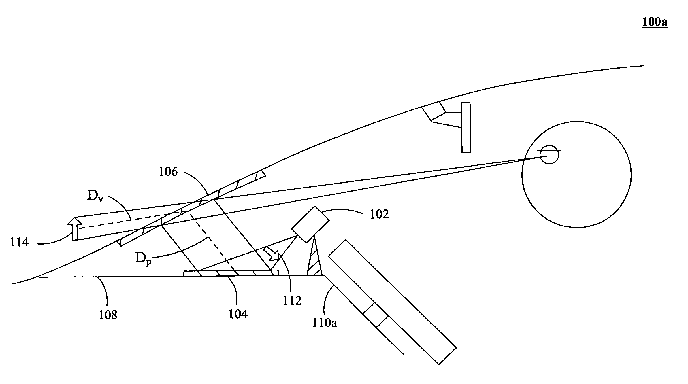
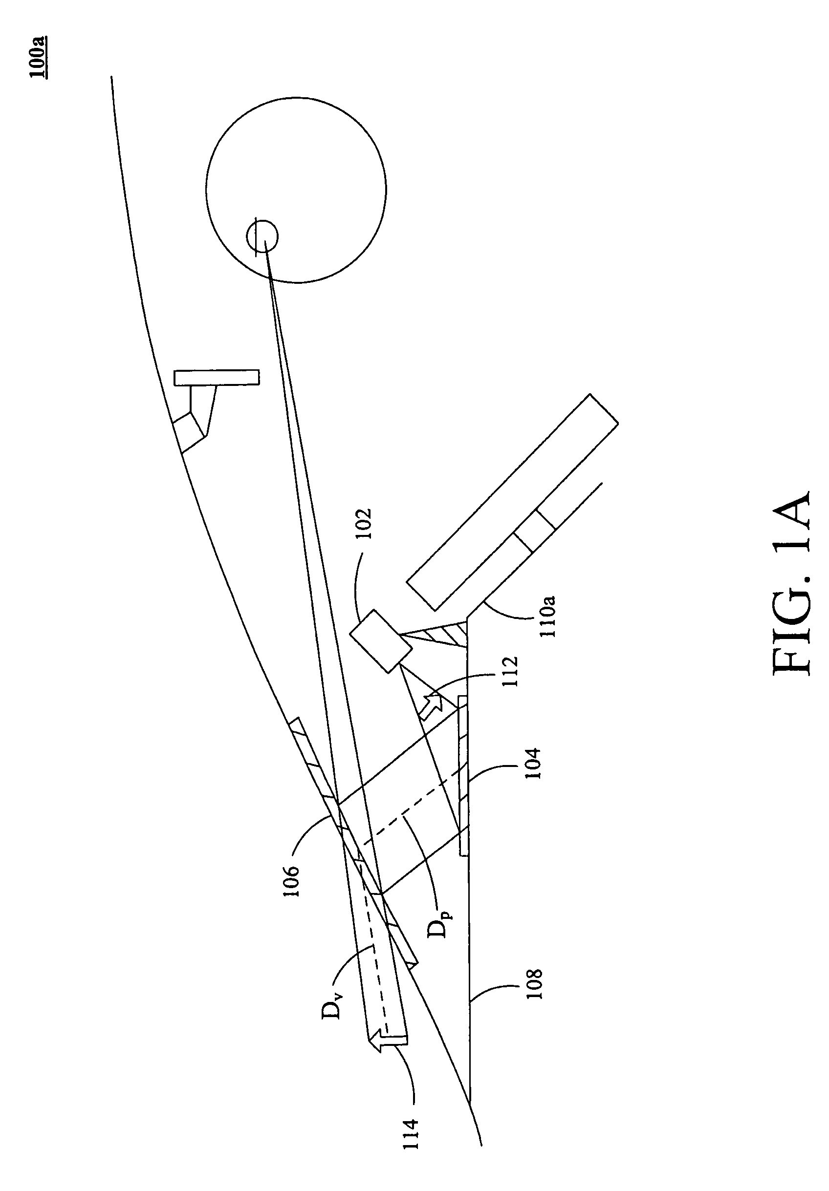
[0016]FIG. 1A is a schematic view of the head-up display system 100a according to the present invention. The head-up display system 100a includes an image projection device 102, a diffusion unit 104, and a frame demonstration medium 106. The image projection device 102 is installed on the instrument panel 110a. The image projection device 102 emits the visible light, e.g. laser beams, to generate a real image 112 on the diffusion unit 104. The diffusion unit 104 receives the visible light emitted from the image projection device 102 to generate the real image 112. The diffusion unit 104 then reflects the received visible light. Further, the diffusion unit 104, such as a diffusion film with gain adjustment, is capable of adjusting the view angle of the visible light and controlling the brightness of the real image 112 on the diffusion unit 104. That is, the diffusion film diffuses the visible light and generates the real image 112 on the diffusion film. The frame demonstration medium...

second embodiment

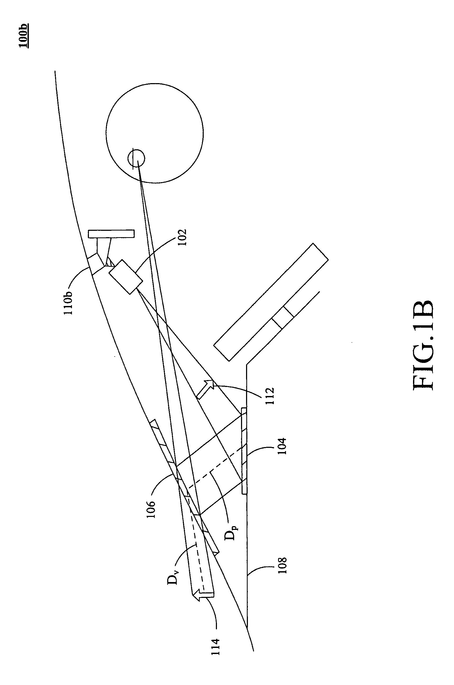
[0020]FIG. 1B is a schematic view of the head-up display system 100b according to the present invention. FIG. 1B is similar to FIG. 1A. The head-up display system 100b includes an image projection device 102, a diffusion unit 104, and a frame demonstration medium 106. The image projection device 102 is installed on the rear-view mirror 110b of the vehicle 108. The image projection device 102 emits the visible light to generate a real image 112 on the diffusion unit 104. The diffusion unit 104 receives the visible light emitted from the image projection device 102 to generate a real image 112. The diffusion unit 104 then reflects the received visible light. Further, the diffusion unit 104, such as a diffusion film with gain adjustment, is capable of adjusting the view angle of the visible light and controlling the brightness of the real image 112 on the diffusion unit 104. The frame demonstration medium 106 receives the visible laser light from the diffusion unit 104. By adjusting th...

third embodiment

[0021]FIG. 1C is a schematic view of the head-up display system 100c according to the present invention. FIG. 1C is similar to FIG. 1A and FIG. 1B. The head-up display system 100c includes an image projection device 102, a diffusion unit 104, and a frame demonstration medium 106. The image projection device 102 is installed on the “A” pole 110c of the vehicle 108. The image projection device 102 emits the visible light to generate a real image 112 on the diffusion unit 104. The diffusion unit 104 receives the visible light emitted from the image projection device 102 to generate a real image 112. The diffusion unit 104 then reflects the received visible light. Further, the diffusion unit 104, such as a diffusion film with gain adjustment, is capable of adjusting the view angle of the visible light and controlling the brightness of the real image 112 on the diffusion unit 104. The frame demonstration medium 106 receives the visible laser light from the diffusion unit 104. By adjustin...


PUM


Abstract

A head-up display system is described. The head-up display system includes an image projection device, a diffusion unit, and a frame demonstration medium. The image projection device emits the visible light, containing text or image information, for generating a real image on the diffusion unit. The frame demonstration medium receives the visible light reflected from the diffusion unit. By adjusting the received visible light reflected from the diffusion unit, the frame demonstration medium generates a virtual image corresponding to the real image. The distance between the real image corresponding to the diffusion unit and the frame demonstration medium is preferably equal to the distance between the virtual image and the frame demonstration medium. Alternatively, the visible light is projected to the frame demonstration medium and then reflected to the diffusion unit. The frame demonstration medium again reflected visible light from the diffusion unit to generate a virtual image corresponding to the real image.

Description

FIELD OF THE INVENTION[0001]The present invention relates to a display system, and more particularly to a head-up display system.BACKGROUND OF THE INVENTION[0002]Head-up display (HUD) systems have been used in a variety of aircrafts, particularly associated with military applications for decades. Recently, more and more similar systems can be found in commercial automobiles. To be able to integrate the head-up display system into the console or the instrument panel of the automobiles, the bulky components of the system, such as the information display module, should be substituted with more compact units, e.g. a projection module, related to the head-up display system. Based on the above requirement, the projection module using laser light source is introduced into the head-up display system. The head-up display system receives the text or image information from the automobile and transfers it into the control signal of the laser light source. Then, the laser light source is project...

Claims


Application Information

Patent Timeline
Patent Type & Authority Applications(United States)
IPC IPC(8): G02B27/01
CPCG02B5/02G02B5/0284G02B5/30G02B2027/0127G02B2027/0118G02B2027/0123G02B27/0101
Inventor HUNG, CHANG-LILIN, TA-WEIYEH, FENG-CHUN
Owner AURISE INVESTMENT CO LTD
Why Eureka
Try Eureka