
Crosstalk Cancellation in Digital Subscriber Line Communications

a digital subscriber and line communication technology, applied in the field of digital communications, can solve the problems of interference in dsl communications, common-mode noise appearing in differential-mode signals, and general noise coupling of common-mode noise onto differential-mode signals, and achieve the effect of modest additional cost and easy implementation

Active Publication Date: 2009-02-05
TEXAS INSTR INC
View PDF12 Cites 36 Cited by
  • Summary
  • Abstract
  • Description
  • Claims
  • Application Information

AI Technical Summary

Benefits of technology

[0017]It is a further object of this invention to provide such circuitry and such a method that can be readily implemented without requiring additional hardware.
[0018]It is a further object of this invention to provide such circuitry and such a method that can be implemented at modest additional cost.

Problems solved by technology

Crosstalk is, of course, noise present on one communications link that results from the coupling, to that link, of signals and noise from other communications links in the physical vicinity.
Indeed, crosstalk and other interference will often dominate the true signal being carried over the DSL link, at a ratio of tens of dB.
However, there is generally some amount of coupling of common-mode noise onto the differential mode signal in modern DSL installations.
This coupling, along with the non-ideal common-mode rejection of modern AFE circuits, results in common-mode noise appearing in the differential-mode signal.
In addition, it has been observed that other interferers in DSL communications, such as narrow-band radio-frequency (RF) interferers, also appear as both common-mode and differential-mode noise.

Method used


Image

  • Crosstalk Cancellation in Digital Subscriber Line Communications
  • Crosstalk Cancellation in Digital Subscriber Line Communications
  • Crosstalk Cancellation in Digital Subscriber Line Communications

Examples


Embodiment Construction

[0030]The present invention will be described in connection with its preferred embodiment, namely as implemented into digital subscriber line (DSL) modulator / demodulator (modem) equipment, and methods of operating the same according to the asynchronous digital subscriber line (ADSL) communications protocols. However, it is contemplated that that this invention will also be beneficial in other loop-based communications systems and protocols in which cross-talk and RF interference limits the signal-to-noise ratio. Accordingly, it is to be understood that the following description is provided by way of example only, and is not intended to limit the true scope of this invention as claimed.

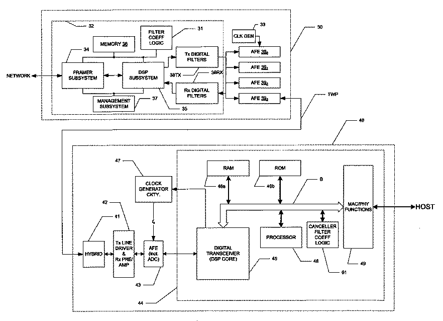
[0031]Referring first to FIG. 3, the construction of an example of central office (CO) modem 30 and customer premises equipment (CPE) modem 40 in a DSL communications link will now be described, by way of example. The architectures of CO modem 30 and CPE modem 40 illustrated in FIG. 3 correspond to mod...


PUM


Abstract

A digital subscriber line (DSL) modem that has a canceller digital filter for cancelling crosstalk and RF interference in a received DSL signal is disclosed. The modem includes common-mode sense circuitry and also differential-mode sense circuitry. Samples of the common-mode signal are acquired during a “quiet” period of initialization of the DSL modem, and samples of the differential-mode signal are acquired during live transmission of a DSL signal. An estimate of an autocorrelation function is obtained from the common-mode samples, and a cross-correlation of the common-mode samples and differential-mode samples is also estimated. Digital filter coefficients are derived from these estimates, based on the assumption that the common-mode samples acquired during the “quiet” phase represent crosstalk and RF interference present during differential-mode communications. The digital filter coefficients can also be updated during showtime of the DSL link, using an expanded number of samples of the common-mode and differential-mode signals.

Description

CROSS-REFERENCE TO RELATED APPLICATIONS[0001]Not applicable.STATEMENT REGARDING FEDERALLY SPONSORED RESEARCH OR DEVELOPMENT[0002]Not applicable.BACKGROUND OF THE INVENTION[0003]This invention is in the field of digital communications, and is more specifically directed to noise cancellation techniques in received digital communications.[0004]Digital Subscriber Line (DSL) technology has become a primary technology providing high-speed Internet access, and now video and telephone communications, in the United States and around the world. As is well known in the art, DSL communications are carried out over existing telephone “wire” facilities, between individual subscribers and a central office (CO) location, operated by a telephone company or an Internet service provider. Typically, some if not all of the length of the loop between the CO and the customer premises equipment (CPE) consists of conventional twisted-pair copper telephone wire. Remarkably, modern DSL technology is able to c...

Claims


Application Information

Patent Timeline
IPC IPC(8): H04B1/10
CPCH04B3/32
Inventor MIRFAKHRAEI, KHASHAYARKIM, YOUNGJAE
Owner TEXAS INSTR INC
Learn More