Vane air-cooling system for automatic transmission torque converter

a technology of torque converter and cooling system, which is applied in the direction of machines/engines, liquid fuel engines, gearing, etc., can solve the problems of increasing cost, increasing vehicle weight, and fuel economy, and achieve the effect of increasing the convective dissipation of hea

Inactive Publication Date: 2009-02-05
GM GLOBAL TECH OPERATIONS LLC
View PDF5 Cites 7 Cited by
  • Summary
  • Abstract
  • Description
  • Claims
  • Application Information

AI Technical Summary

Benefits of technology

[0009]According to a first embodiment of the present invention, a vane air-cooling system is provided for a torque converter assembly having a housing shell and a flex plate. The vane air-cooling system includes a housing cover having opposing exterior and interior surfaces which define a rotatable base portion and a wall portion. The base portion is fixedly attached to the flex plate, whereas the wall portion extends from an outer periphery of the base portion and is configured to attach to the housing shell. The vane air-cooling system also includes a plurality of vane members positioned along the outer periphery of the base portion, preferably evenly spaced between the flex plate and the housing shell. The vane members are configured to increase the convective dissipation of heat from the torque converter assembly to surrounding ambient air when the base portion rotates. Ideally, the base portion is substantially circular, wherein the wall portion extends substantially perpendicular from the base portion in a continuous manner about the base portion's periphery.
[0010]Preferably, each vane has a crown portion and a bottom portion connected to each other by opposing first and second edges and opposing first and second faces. The bottom portion operatively connects each vane to the base portion.
[0011]Optimally, the vanes have a turbine tin configuration, wherein the first and second edges are oriented radially out-of-plane relative to a true radius extending from a center of the housing cover. In this instance it is also preferred that the first and second surfaces have a convex profile relative to the true radius. In addition, the first and second edges have a convex profile relative to the base portion.
[0012]Alternatively, the vanes preferably have a curved fin configuration, wherein the first and second edges are oriented radially out-of-plane relative to a true radius extending from the center of the housing cover. In this instance it is also preferred that the first and second surfaces have a convex profile relative to the true radius.
[0013]According to yet another alternate, the vanes preferably have a straight-in configuration, wherein the first and second edges are oriented radially-in-plane relative to a true radius extending from the center of the housing cover. In this instance it is also preferred that the first and second surfaces extend substantially perpendicular from the base portion.
[0014]Preferably, the exterior and interior surfaces also include a centering pilot extending substantially perpendicular from the base portion. The centering pilot is configured to coaxially position the torque converter assembly with the flex plate.

Problems solved by technology

However, such additional componentry leads to increased costs and added vehicle weight (which leads to decreased fuel economy.)

Method used


Image

  • Vane air-cooling system for automatic transmission torque converter
  • Vane air-cooling system for automatic transmission torque converter
  • Vane air-cooling system for automatic transmission torque converter

Examples


Embodiment Construction

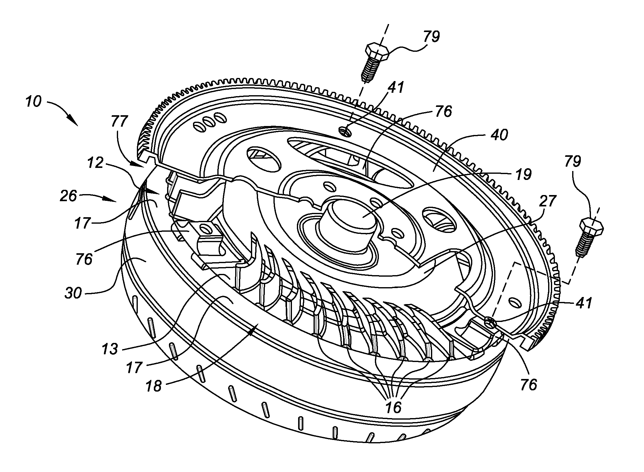
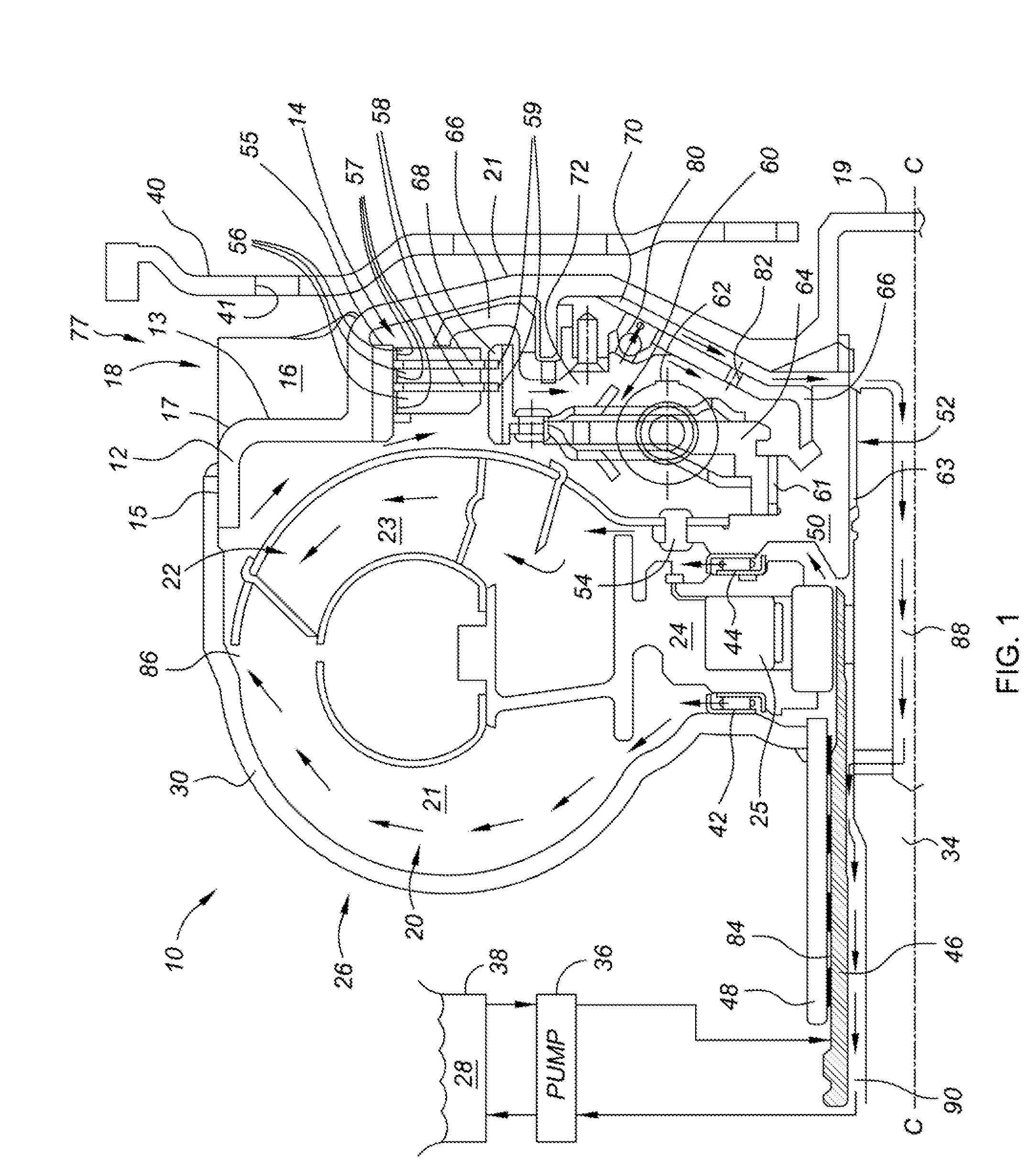
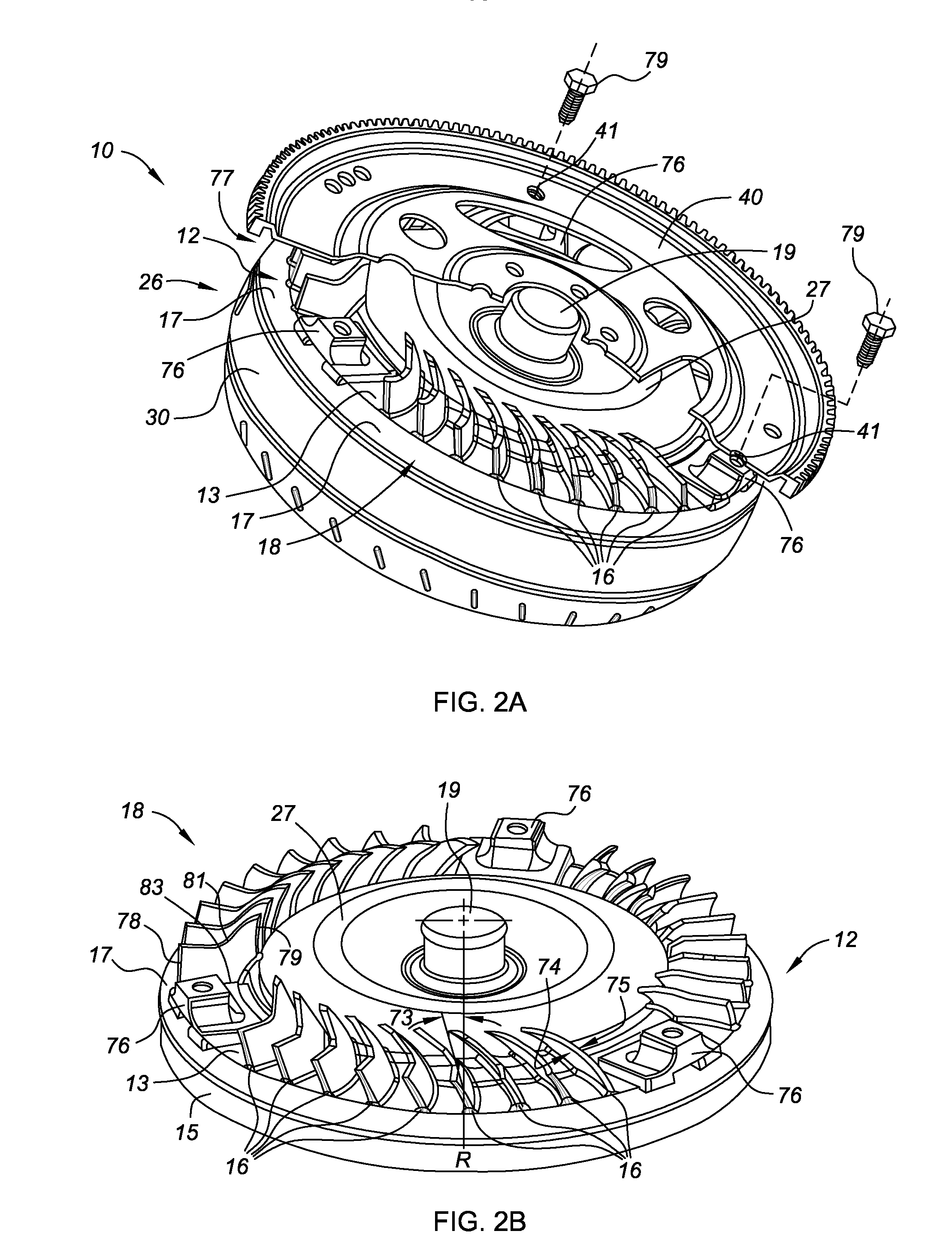
[0027]Referring to the drawings, wherein like reference number refer to the same or similar components throughout the several views, FIG. 1 is a cross-sectional side-view of a portion of an exemplary hydrodynamic torque converter assembly, identified generally as 10, in accordance with the present invention. The torque converter assembly 10 is preferably adapted lo be operatively positioned between a prime mover, such as an internal combustion engine (not shown), and an automatically shifted multi-speed power transmission (not shown.) The torque converter assembly 10 can also be incorporated into other types of vehicles (e.g., hybrid vehicles, electric vehicles, etc.) across various platforms (e.g., passenger car, light truck, heavy duty, and the like.)

[0028]The exemplary torque converter assembly 10 of FIG. 1 includes an electronically controlled converter clutch (hereinafter “ECCC”) 14, a torque converter pump or impeller 20, a bladed turbine 22, and a stator 24. The impeller 20 i...


PUM


Abstract

A cooling system is provided for automatic transmission torque converter assemblies having a housing shell and flex plate. The cooling system includes a housing cover having opposing exterior and interior surfaces that define a wall portion and a preferably circular base portion. The base portion is configured to attach to the flex plate, preferably by one or more stud members, to be rotated thereby. The wall portion extends from a periphery of the base portion and is configured to attach to the housing shell. The cooling system also includes a plurality of vane members positioned along the outer periphery of the base portion. The vane members are configured to increase convective dissipation of heat from the torque converter assembly to surrounding ambient air by increasing the heat transfer coefficient and surface area. Optimally, the vanes have a turbine fin configuration, but may alternatively have curved fin or a straight-fin configuration.

Description

TECHNICAL FIELD[0001]The present invention relates generally to torque converter devices for automatic transmissions, and more specifically to cooling systems for torque converter devices and torque converter clutches.BACKGROUND OF THE INVENTION[0002]Most conventional motorized vehicles include a powertrain that has a power source, such as an internal combustion engine, connected to a multi-speed power transmission that is adapted to manipulate and transmit power from the engine to a final drive (e.g., driveshaft, differential, and wheels) for propelling the vehicle. Traditional powertrains having an automatic transmission generally include a hydrodynamic input device, such as a torque converter, positioned between the engine and the transmission. The torque converter is a hydrokinetic fluid coupling employed predominantly to allow the engine to run without stalling when the vehicle wheels and transmission gears come to a stop, and to provide torque multiplication in the lower speed...

Claims


Application Information

Patent Timeline
Patent Type & Authority Applications(United States)
IPC IPC(8): F04D29/44F04D29/54
CPCF16H41/30F16H2045/0284F16H45/02
Inventor SAMIE, FARZADVAHABZADEH, ARSHIA
Owner GM GLOBAL TECH OPERATIONS LLC
Why Eureka
Try Eureka