High-power LED lamp

A LED lamp, high-power technology, applied in cooling/heating devices of lighting devices, lighting and heating equipment, electrical components, etc., can solve problems such as short service life, pollute the environment, and consume a lot of power, and achieve improved heat dissipation. Small size, energy saving effect

Inactive Publication Date: 2010-09-22
杨振行
View PDF5 Cites 1 Cited by
  • Summary
  • Abstract
  • Description
  • Claims
  • Application Information

AI Technical Summary

Problems solved by technology

[0002] Traditional incandescent or fluorescent lamps consume a lot of power, have a short service life, pollute the environment, and are easily damaged

Method used


Image

  • High-power LED lamp
  • High-power LED lamp

Examples


Embodiment 1

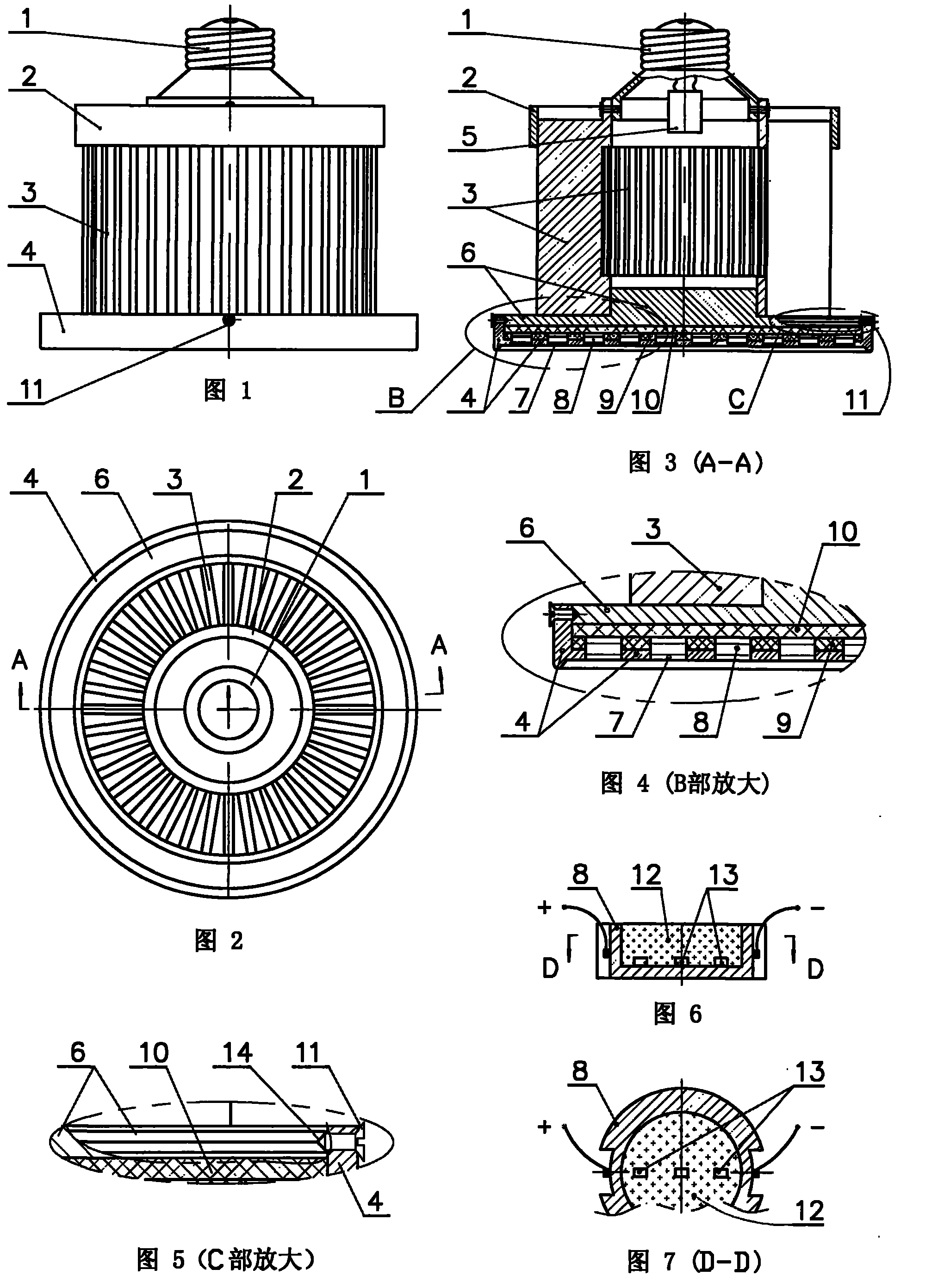
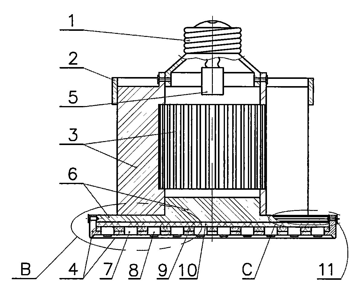
[0016] Example 1 as figure 1 Shown in -7: a high-power LED lamp, including a lamp cap 1 and a constant current drive circuit board 5 located therein, a heat sink 3, a thermally conductive insulating sheet, a reflector 4 and an LED chip packaging bracket 8; the heat sink 3 is It consists of the upper part and the lower part of the inner cavity respectively connected into one, and the metal sheets arranged radially upright to form a cylinder. The heat dissipation tube 3 is positioned and connected with the lamp head 1; the inner diameter of the middle part of the cylindrical inner cavity of the heat dissipation tube 3 is larger than the inner diameter of the upper end and the lower end. , There is a gap between the metal sheets in the middle of the inner cavity of the cooling tube 3, and they are not close to each other. The inner cavity of the cooling tube 3 is transparent to the outer wall through the gap between the metal sheets arranged radially upright, so as to facilitate a...

Embodiment 2

[0017] Embodiment 2: A high-power LED lamp as described in Embodiment 1, the apron at the bottom of its heat-conducting bottom plate 6 is rectangular. The LED chip 13 and the fluorescent powder and the silica gel mixture 12 covering the LED chip 13 are placed in the LED chip packaging bracket 8. The bottom area of ​​the fluorescent powder and the silica gel mixture 12 coverage area is 20 times the surface area of ​​the LED chip 13, which can be greatly improved. Improve luminous efficiency and reflective efficiency.


PUM


Abstract

The invention relates to a high-power LED lamp which comprises a lamp cap, a heat radiating barrel, a heat-conducting insulating strip, a reflecting plate and an LED chip packaging support; the heat radiating barrel consists of metal sheets which are radially and vertically arranged into a circular barrel, wherein the upper parts and the lower parts of the inner cavities of the metal sheets are connected into a whole and metal sheets; the heat radiating barrel is connected with the lamp cap in a positioning manner, and gaps are formed among the metal sheets at the middle part of the inner cavity of the heat radiating barrel and are not mutually stuck together so as to be convenient for air convection for heat emission; a ferrule is fastened at the upper part of the outer wall of the heatradiating barrel, has the function of a chimney with air draught and further improves the heat radiating effect; and a heat-conducting base plate is fastened at the lower end of the inner cavity of the heat radiating barrel, the LED chip packaging support is installed in a slot opening where a base plate of the reflecting plate and the heat-conducting insulating strip with holes are mutually aligned, LED chips, and fluorescent powder for covering the LED chips and silica gel mixture are put in the LED chip packaging support, and the basal area of the coverage area of the fluorescent powder and the silica gel mixture is 10-30 times of the surface area of the LED chips, therefore, the luminescent efficiency and the reflecting efficiency can be greatly improved.

Description

technical field [0001] The invention relates to a lighting fixture, in particular to a high-power LED lamp with good heat dissipation effect and high luminous efficiency. Background technique [0002] Traditional incandescent or fluorescent lamps consume a lot of power, have a short service life, pollute the environment, and are easily damaged. LED is a semiconductor solid-state light-emitting device, which consumes less power, has a long service life, is environmentally friendly, and is not easily damaged. The promotion of LED lights can save a lot of power and reduce lighting costs. One of the key issues of high-power LED lamps is how to improve the heat dissipation effect, and the second is how to improve the luminous efficiency. Contents of the invention [0003] The technical problem to be solved by the present invention is to provide a high-power LED lamp with good heat dissipation effect and high luminous efficiency. [0004] In order to solve the above technical ...

Claims


Application Information

Patent Timeline
Patent Type & Authority Patents(China)
IPC IPC(8): F21S2/00F21V29/00F21V7/05F21V19/00F21V9/10H01L23/367F21Y101/02F21K9/23F21V9/40F21V29/77F21Y115/10
Inventor 杨振行
Owner 杨振行
Why Eureka
Try Eureka