
Simulation of program execution to detect problem such as deadlock

a program execution and deadlock technology, applied in error detection/correction, instruments, computing, etc., can solve problems such as datarace, processing halt, datarace, and deadlock between more than two processes

Inactive Publication Date: 2009-02-05
CYPRESS SEMICON CORP
View PDF35 Cites 58 Cited by
  • Summary
  • Abstract
  • Description
  • Claims
  • Application Information

AI Technical Summary

Benefits of technology

[0019]According to at least one embodiment, a simulator program inclusive of a hardware model implemented as software is provided with the function to detect overlapping accesses made to an identical resource as a monitor function separate from the hardware model. With this arrangement, it is possible to provide a simulation method and simulator that can detect datarace, deadlock, and the like without modifying a program for debugging purposes when program execution is simulated on an LSI software model.

Problems solved by technology

Datarace refers to an error that occurs as a result of multiple accesses to a single variable due to the failure to perform proper exclusive access control.
Deadlock refers to an error in which two threads hold resources required by each other so as to wait for the release of resources, for example, resulting in a processing halt due to the failure of either thread to release its resource.
Accordingly, both the process A and the process B are in the waiting state, resulting in a processing halt.
In actual processing, however, datarace and deadlock may also occur between more than two processes.
Regardless of the number of processes, datarace and deadlock often cause a system operation failure, causing a significant drop in system performance.
In the case of LSIs embedded in electronic equipments such as consumer products, however, the device configuration is relatively simple, so that the provision of complex debug functions causing a cost increase is not desirable.
Such modifications to a program, however, cause an actually executed program to be different from the program intended to be debugged in terms of its operating environment and conditions.
Such debugging thus fails to debug an actual operation of an actual program.

Method used


Image

  • Simulation of program execution to detect problem such as deadlock
  • Simulation of program execution to detect problem such as deadlock
  • Simulation of program execution to detect problem such as deadlock

Examples


Embodiment Construction

[0053]In the following, embodiments of the present invention will be described with reference to the accompanying drawings.

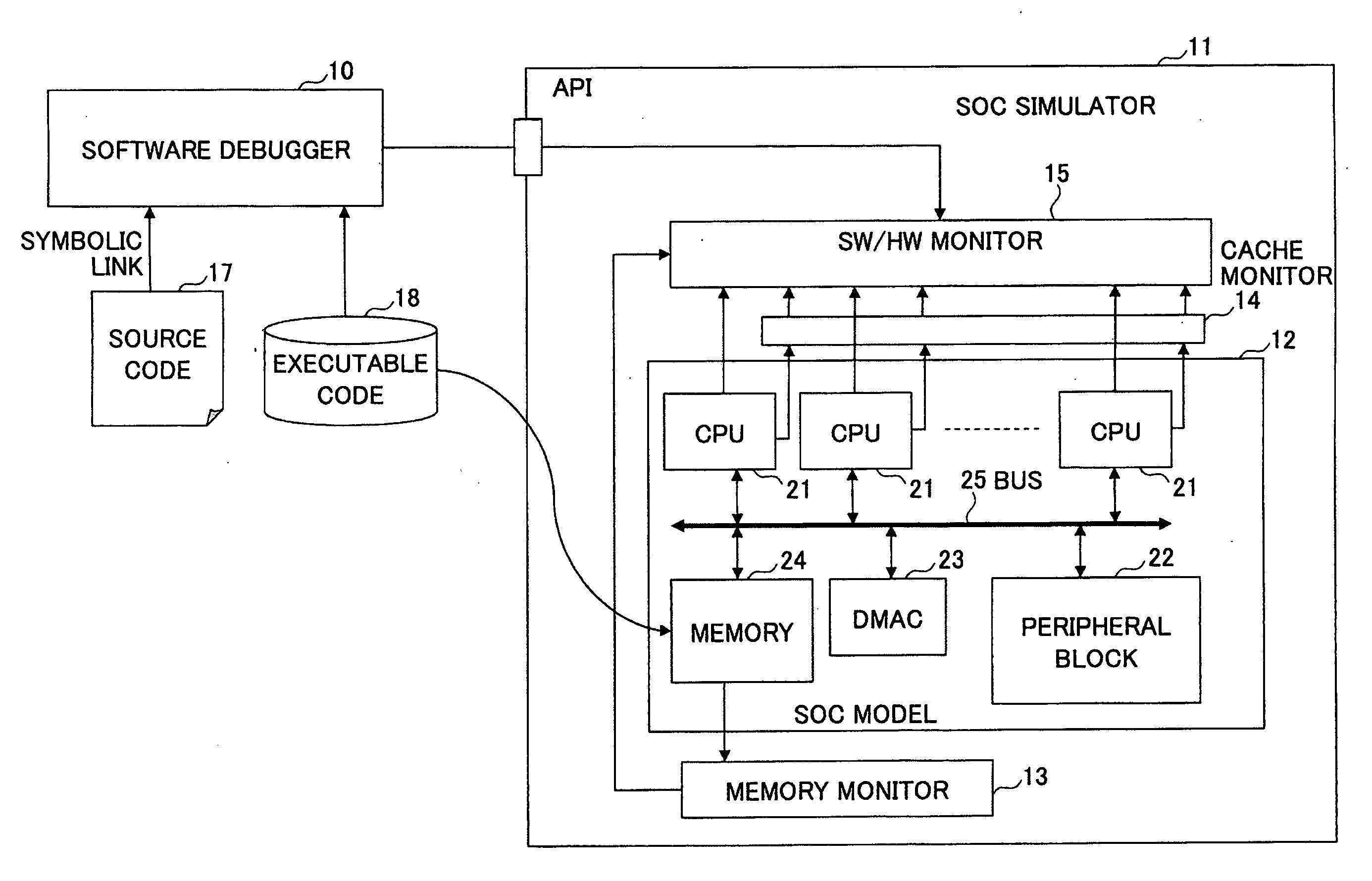
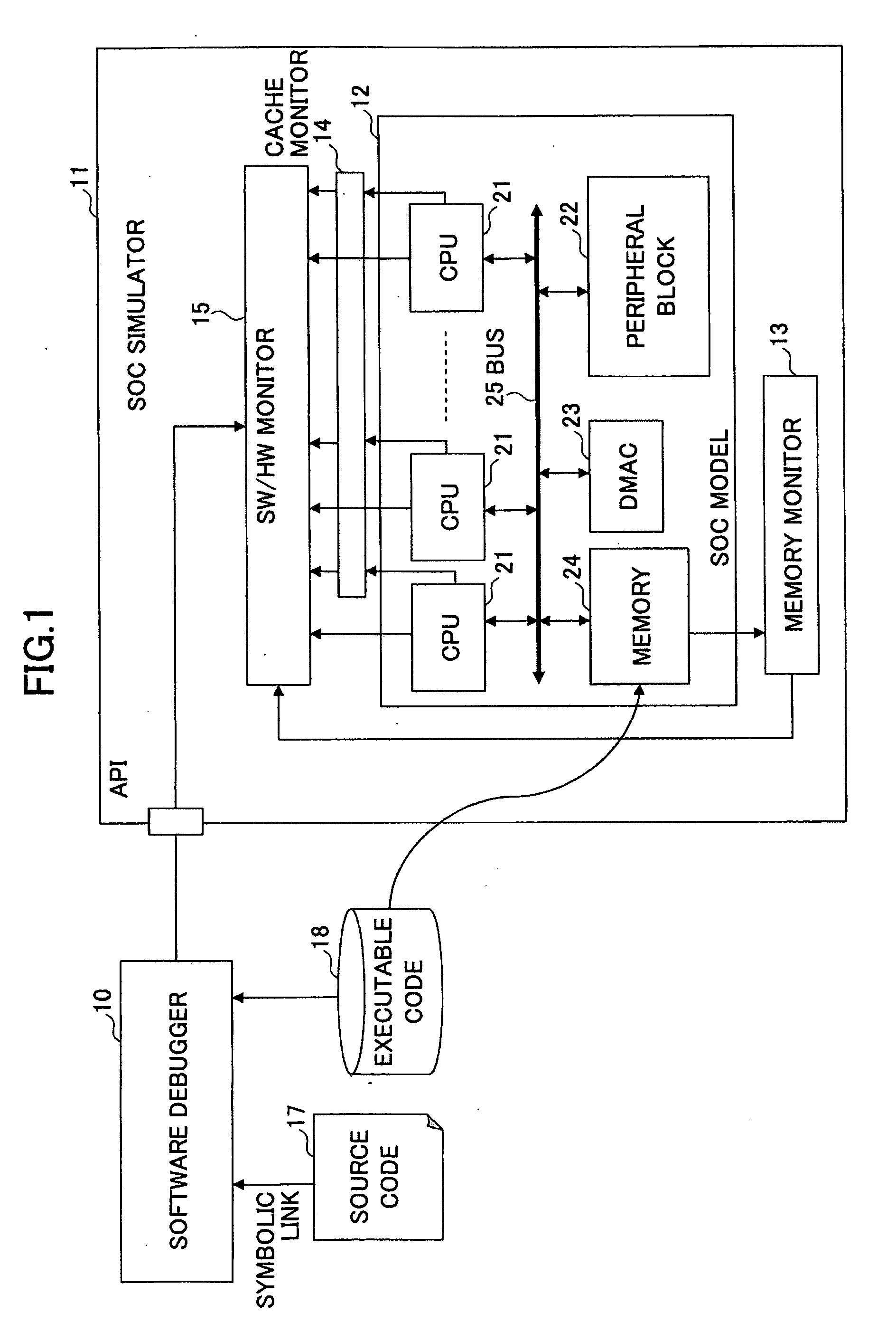
[0054]FIG. 1 is a drawing showing an example of a configuration in which an SoC simulator is used. The configuration shown in FIG. 1 includes a software debugger 10 and an SoC simulator 11. The SoC simulator 11 is coupled to the software debugger 10 via an API (Application Program Interface), and includes an SoC model 12, a memory monitor 13, a cache monitor 14, and an SW / HW (software / hardware) monitor 15. The SoC model 12 is a software model of a system LSI. The SoC model 12 includes one or more CPUs 21, a peripheral block 22, a DMAC 23, a memory 24, and a bus 25, all of which are implemented as software. The software debugger 10 and the SoC simulator 11 are executed on a computer.

[0055]A source code 17 of a program to be executed on the system LSI implemented as the SoC model 12 is generated and compiled by the computer to produce an executable code 18. The so...


PUM


Abstract

A method of simulating software by use of a computer includes executing a program inclusive of a plurality of threads by a hardware model implemented as software on a software simulator, utilizing a monitor function of the simulator to collect information about accesses by monitoring accesses made by the plurality of threads with respect to resources provided in the hardware model, utilizing the monitor function to detect, from the collected information, overlapping accesses made to an identical resource area by two or more of the threads, and utilizing the monitor function to generate a message for warning of the overlapping accesses.

Description

CROSS-REFERENCE TO RELATED APPLICATIONS[0001]The present application is based upon and claims the benefit of priority from the prior Japanese Patent Application No. 2007-198001 filed on Jul. 30, 2007, with the Japanese Patent Office, the entire contents of which are incorporated herein by reference.BACKGROUND OF THE INVENTION[0002]1. Field of the Invention[0003]The disclosures herein generally relate to computer-aided design, and particularly relate to the detection of problems such as a deadlock occurring during the execution of programs on a system LSI.[0004]2. Description of the Related Art[0005]In developing a parallel program that runs on a single-processor or multi-processor system, there is a need to accurately detect the occurrence of datarace and deadlock. Based on the detected dataraces and deadlocks, the software engineer modifies the program to remove the causes of such occurrences.[0006]Datarace refers to an error that occurs as a result of multiple accesses to a single...

Claims


Application Information

Patent Timeline
IPC IPC(8): G06F9/44
CPCG06F9/524G06F11/3664G06F11/3632G06F11/3457
Inventor TATSUOKA, MASATOIKE, ATSUSHI
Owner CYPRESS SEMICON CORP
Learn More