Turbo fan for blowing and refrigerator having the same

a technology for refrigerators and fans, applied in the direction of wind motors with parallel air flow, wind motors with perpendicular air flow, liquid fuel engine components, etc., to achieve the effect of minimizing power consumption and noise, and improving blowing efficiency

Inactive Publication Date: 2009-02-12
LG ELECTRONICS INC
View PDF8 Cites 8 Cited by
  • Summary
  • Abstract
  • Description
  • Claims
  • Application Information

AI Technical Summary

Benefits of technology

[0008]Therefore, it is an object of the present invention to provide a turbofan for blowing capable of improving a blowing efficiency for cool air and minimizing power consumption and noise, and a refrigerator having the same.

Problems solved by technology

Even if the turbofan 9 maintains an inner temperature of the refrigerater, it causes noise.

Method used


Image

  • Turbo fan for blowing and refrigerator having the same
  • Turbo fan for blowing and refrigerator having the same
  • Turbo fan for blowing and refrigerator having the same

Examples


Embodiment Construction

[0034]Hereinafter, a turbofan for blowing and a refrigerator according to the present invention will be explained in more detail.

[0035]As shown in FIGS. 3 to 5, the turbofan for blowing comprises: a base plate 110 of a disc shape having a hub 111 protruding from a center thereof; a plurality of blades 120 disposed on an outer circumerential surface of the base plate 110 with a constant interval therebetween in a circumferential direction, for blowing cool air introduced from the hub 111 in a radial direction; and a shroud 130 connected to the blades 120 in opposition to the base plate.

[0036]A circle that is obtained by connecting outer ends of the respective blades 120 in a radial direction corresponds to an outer circumference of the shroud 130, and is more protruding than an outer circumference of the base plate 110. That is, a diameter (Do) of a circle that is obtained by connecting outer ends of the respective blades 120 is equal to an outer diameter of the shroud 130, but is la...


PUM


Abstract

A turbofan for blowing comprises: a base plate having a hub protruding from a center thereof; a plurality of blades disposed on an outer circumerential surface of the base plate with a constant interval therebetween in a circumferential direction; and a shroud connected to the blades in opposition to the base plate. An outer diameter of a fan, a height of the blade, an inner diameter of the blade, an inner diameter of the shroud, an entrance angle of the blade, etc. are designed with an optimum condition, there by improving a blowing efficiency for cool air and reducing power consumption and noise.

Description

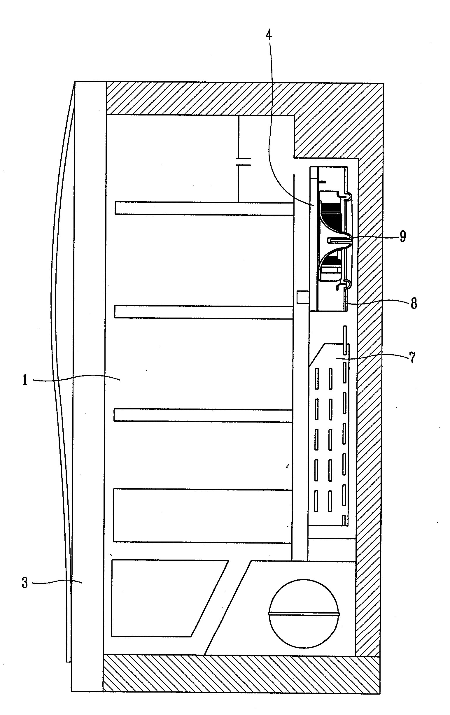
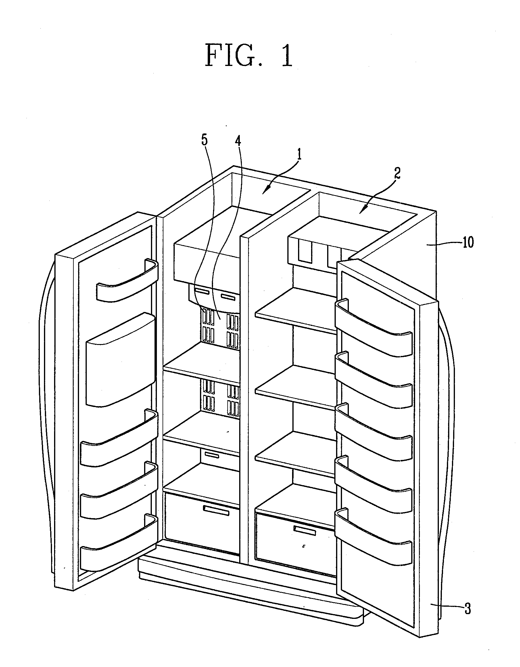
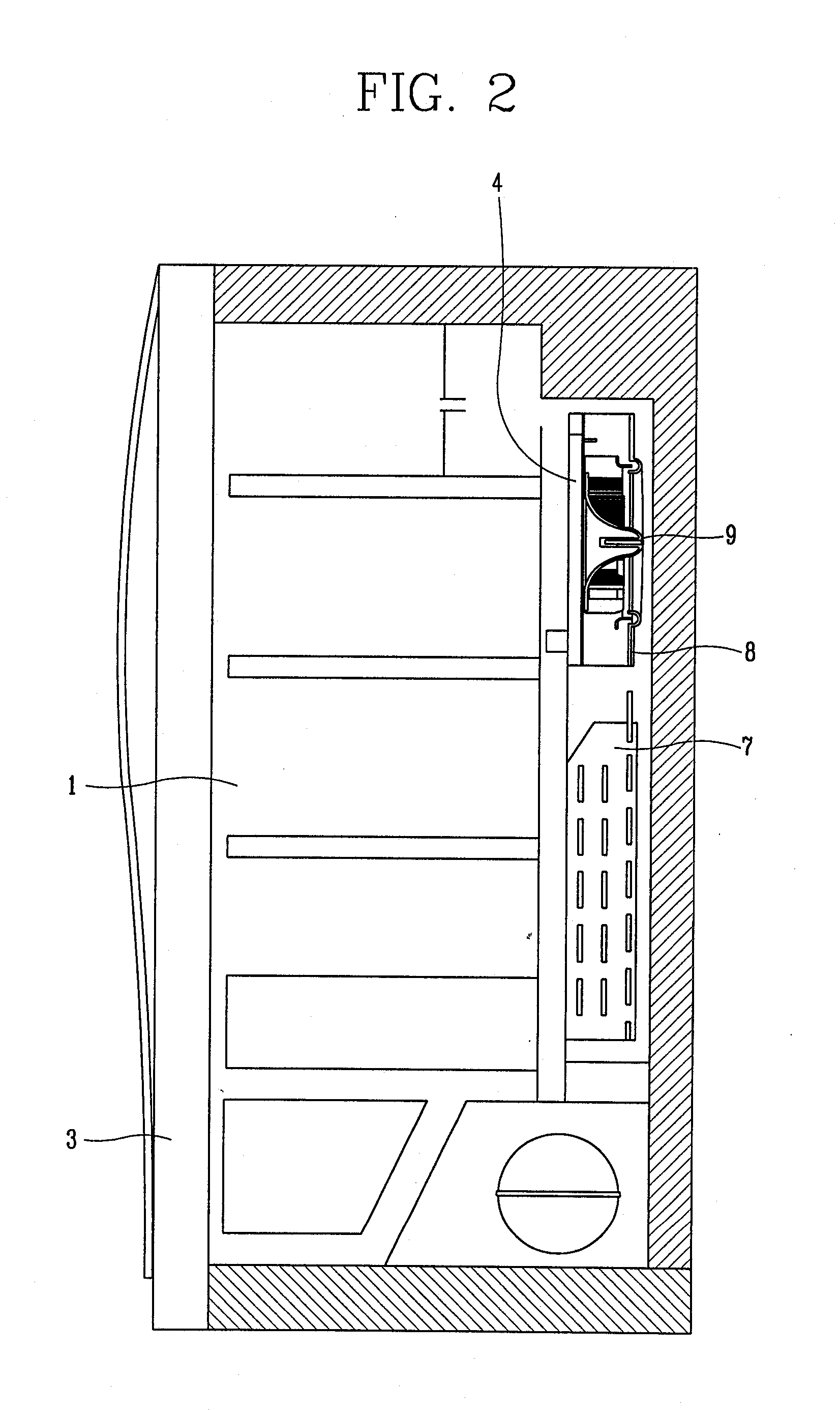
TECHNICAL FIELD[0001]The present invention relates to a turbofan for blowing and a refrigerator having the same, and more particularly, to a turbofan for blowing capable of improving a blowing efficiency for cool air and minimizing power consumption and noise, and a refrigerator having the same.BACKGROUND ART[0002]In general, a refrigerator serves to store foodstuffs as a freezing state or a refrigerating state by circulating cool air generated by a refrigerating cycle.[0003]As shown in FIG. 1, the conventional refrigerator comprises a body 10 having a freezing chamber 1 and a refrigerating chamber 2, and a door 3 disposed at a front surface of the body 10 for opening and closing the freezing chamber 1 and the refrigerating chamber 2.[0004]As shown in FIG. 2, a turbofan 9 for forcibly blowing air cooled through an evaporator 7 into the freezing chamber 1 is installed at a rear side of the body 10. A shroud 8 for introducing air blown by the turbofan 9 into the freezing chamber 1 is ...

Claims


Application Information

Patent Timeline
Patent Type & Authority Applications(United States)
IPC IPC(8): F25D17/06F01D5/22F04D17/08
CPCF04D29/282F25D2317/0683F25D17/06F04D29/666
Inventor BAE, JUN-HOKIM, CHANG-JOON
Owner LG ELECTRONICS INC
Why Eureka
Try Eureka