
Photoacoustic free field detector

a detector and free field technology, applied in the field of photoacoustic free field detectors, can solve the problems of reducing the measurement sensitivity, unable to carry out free field measurements, and engendering the sound pressure of the microphone by absorption

Inactive Publication Date: 2009-02-12
FRAUNHOFER GESELLSCHAFT ZUR FOERDERUNG DER ANGEWANDTEN FORSCHUNG EV
View PDF22 Cites 13 Cited by
  • Summary
  • Abstract
  • Description
  • Claims
  • Application Information

AI Technical Summary

Benefits of technology

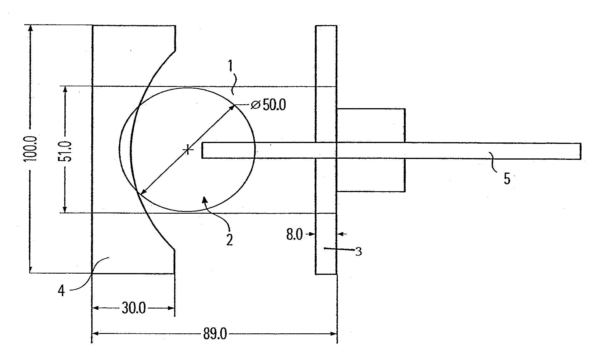
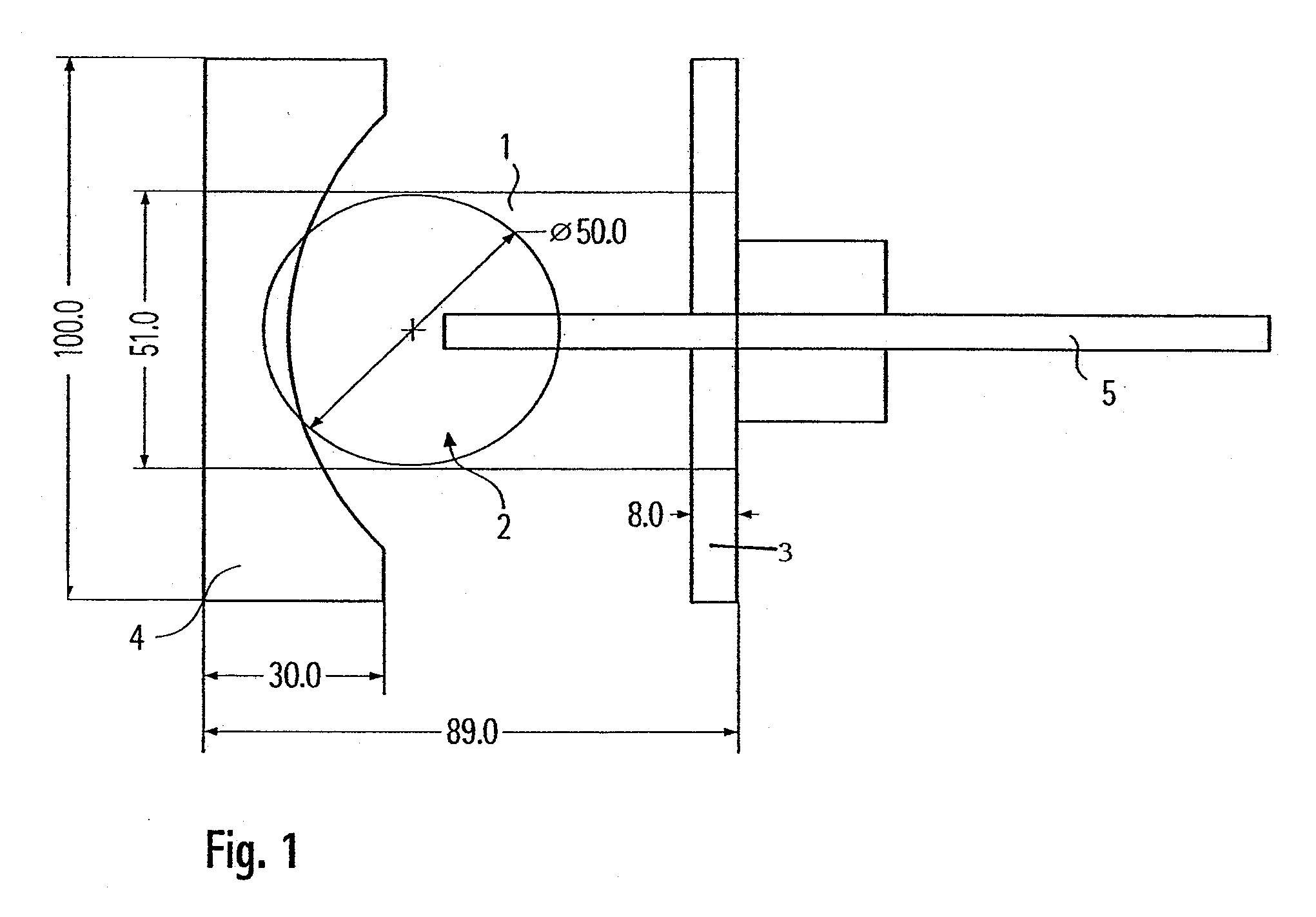
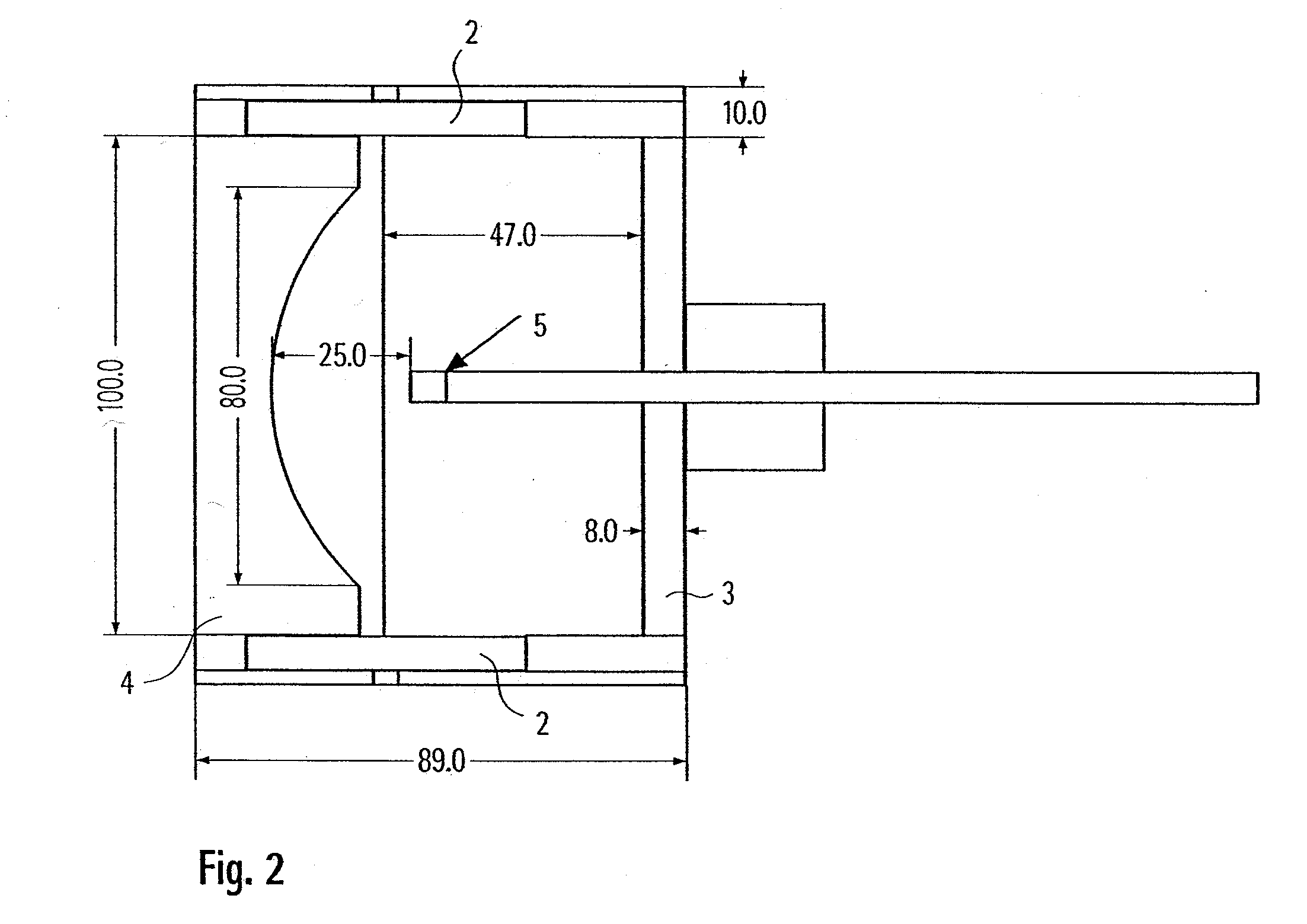
[0017]This photoacoustic detector includes an arrangement for the introduction of excitation light into the measuring area so that the excitation light can be absorbed by the absorbent materials located in the measuring area with the production of acoustic energy. Furthermore, at least one acoustic sensor is provided. The detector is distinguished by the fact that an arrangement for the concentration of the acoustic energy is present. With these arrangements, a local maximum of the sound pressure can be achieved at least at one position. Here, a local maximum of the sound pressure is to be understood as a position at which the sound pressure is perceptibly increased in comparison to the immediate environment. The at least one acoustic sensor is then arranged in the vicinity of the at least one position at which the local maximum of the sound pressure produced is present or can be produced. The concentration of the sound pressure produced enables measurements also to be taken in an acoustically open measuring area with sufficient sensitivity. In this manner, the above-described advantages of photoacoustic detectors with acoustically open measuring area are achieved, without, however, having to accept an undesirable reduction of the sound pressure at the acoustic sensor.
[0019]A further enhancement of the photoacoustic signal obtained can be achieved if optically reflecting elements are so arranged that the excitation light can pass through the measuring area several times. In this case, a higher level of energy is absorbed, which then leads to a correspondingly higher level of sound production.
[0032]The photoacoustic detector described, and a method with which absorbent materials are detected using the photoacoustic detector, are well-suited for the monitoring of the air quality in internal spaces, in particular for the monitoring of air that is sucked into ventilation systems for internal spaces. This is because a wide range of measurements can be covered with photoacoustic detection for a very wide variety of absorbent materials that can be troublesome in internal spaces. For ventilation devices, it is furthermore necessary that complex sampling can be avoided, since rapid adaptation of the ventilation to the detected concentrations of contaminants is desirable.

Problems solved by technology

The absorption in the windows can also have the disadvantage that as a result of the absorption an undesirable photoacoustic background signal is produced; this is overlaid on the measurement signal and thus reduces the measurement sensitivity.
With a measurement arrangement of this kind, however, it is not possible to carry out free field measurements, which give a better mapping of the actual loading of the air with the absorbent materials.
In photoacoustic detectors of this kind, however, the sound pressure on the microphone engendered by the absorption is already so weakened that the measurement sensitivity is reduced in an undesirable manner.

Method used


Image

  • Photoacoustic free field detector
  • Photoacoustic free field detector
  • Photoacoustic free field detector

Examples


Embodiment Construction

[0015]The present invention provides for an acoustically open photoacoustic-free field detector in which a sufficient sound pressure is present at the acoustic sensor. The invention furthermore provides a corresponding acoustic measurement method.

[0016]A photoacoustic detector is provided with an acoustically open measuring area not completely surrounded by a housing. In following description, a measuring area is to be understood as an area in which the sound pressure produced by the absorption can escape from the inlets and outlets, of relatively large embodiment, for the sample air.

[0017]This photoacoustic detector includes an arrangement for the introduction of excitation light into the measuring area so that the excitation light can be absorbed by the absorbent materials located in the measuring area with the production of acoustic energy. Furthermore, at least one acoustic sensor is provided. The detector is distinguished by the fact that an arrangement for the concentration of...


PUM


Abstract

The invention relates to a photoacoustic detector including an acoustically open measuring area which is not completely surrounded by a housing. The detector includes an arrangement for introducing excitation light into the measuring area, such that the excitation light can be absorbed by absorbent materials which are located in the measuring area and which are used to produce acoustic energy. The invention also relates to a detector which includes at least one acoustic sensor and an arrangement is provided in order to concentrate the acoustic energy, in order to reach a local maximum of the acoustic pressure on at least one position. The at least one sensor is arranged in the vicinity of the at least one position, whereon the local maximum of the produced acoustic pressure is present or can be produced. The invention also relates to an associated method.

Description

BACKGROUND OF THE INVENTION[0001]1. Field of the Invention[0002]The invention concerns a photoacoustic free field detector. With a photoacoustic detector of this kind even a small quantity of trace gases is to be detected in a simple manner without complex sampling.[0003]2. Description of Background and Other Information[0004]Photoacoustic detection takes place in that excitation light is absorbed by absorbent materials. As a result, heating takes place. The heating leads to an expansion, especially if gases are being heated. Here the heating of the gases can also take place indirectly, for example by means of heated solid particles that heat the ambient gas. If the heating and the resulting expansion take place sufficiently rapidly, sound is produced that can be detected with an acoustic sensor, such as a microphone. The detected sound is thus a measure of the energy absorbed that depends on the intensity of the excitation light and also on the kind and concentration of the absorbe...

Claims


Application Information

Patent Timeline
IPC IPC(8): G01N29/02
CPCG01N21/1702G01N2291/02809G01N2021/1704
Inventor BREUER, KLAUSKUNG, ANDREW H.MIKLOS, ANDRASANGSTER, JUDITSEDLBAUER, KLAUS
Owner FRAUNHOFER GESELLSCHAFT ZUR FOERDERUNG DER ANGEWANDTEN FORSCHUNG EV
Learn More