Engine head cover assembly having an integrated oil separator and a removable cover

a technology of oil separator and engine head cover, which is applied in the direction of lubrication of auxiliaries, combustion engines, casings, etc., can solve the problems of increasing oil consumption

Inactive Publication Date: 2009-02-12
TOYOTA MOTOR CO LTD
View PDF5 Cites 24 Cited by
  • Summary
  • Abstract
  • Description
  • Claims
  • Application Information

AI Technical Summary

Problems solved by technology

This results in an increase in oil consumption.

Method used


Image

  • Engine head cover assembly having an integrated oil separator and a removable cover
  • Engine head cover assembly having an integrated oil separator and a removable cover
  • Engine head cover assembly having an integrated oil separator and a removable cover

Examples


second embodiment

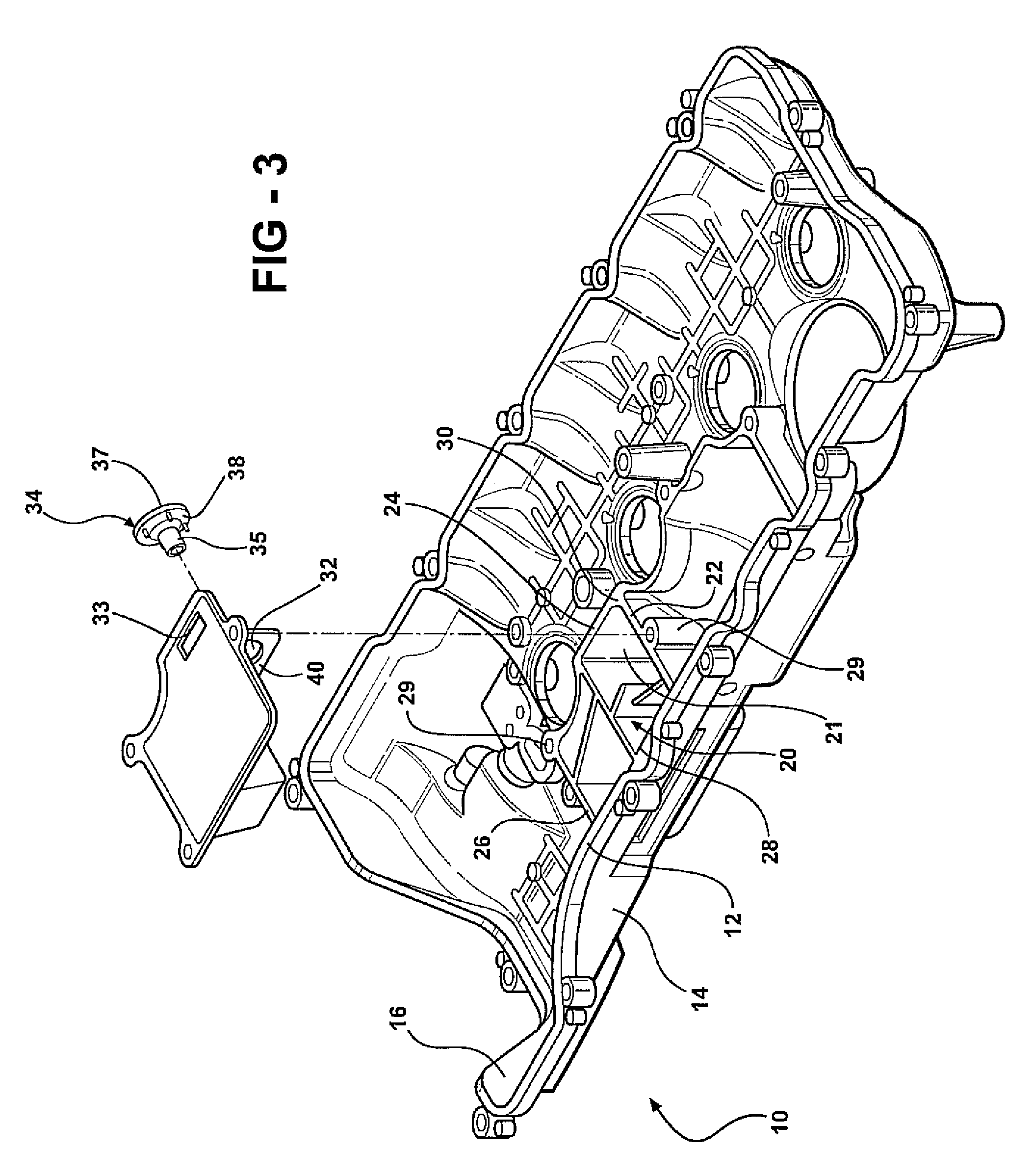
[0028]the head cover assembly 110 is shown in FIGS. 4-8, wherein like parts are indicated by numerals offset by 100. In the second preferred embodiment, the head cover 112 includes a cap 160 with an intake port 170. The cap 160 is configured to engage the head cover 112 so as to enclose the oil separator 120. The intake port 170 allows manifold vacuum to draw crankcase gases from the crankcase and through the oil separator 120. The cover 130 is disposed between the cap 160 and cylindrical side wall 150 of the oil separator 120, which together define an interior space 121 interconnected to the oil separator 120 by an aperture 133. More specifically, the cylindrical side wall 150 is integrally formed with the head cover 112 and defines a recess 152 for receiving the cap 160 therein. The cap 160 may further include an annular portion with threads 162 for engaging mating threads 164 on the head cover 112. Thus it is inherent that the cover 130 or valve 134 may be easily replaced by simp...

first embodiment

[0030]With reference again to FIGS. 7 and 8, the valve 134 is configured the same as in the first preferred embodiment. The valve 134 is disposed within the cover wall aperture 132 such that the tubular body 135 extends through the cover wall aperture 132 and away from aperture 133. As in the first embodiment, and the annular surface 138 is spaced apart from the cover wall 140. The valve 134 is fixed to the cover wall 140 in the same manner as described above. However, the as the cover 130 is disposed above the oil separator 120, crankcase gases are first passed through the oil separator 120 before reaching the cover 130. Thus, as crankcase gases are drawn from the engine and through the oil separator 120, the crankcase gases are directed through aperture 132 into the interior space of the cap 160 through the valve opening 18. Oil remaining in the crankcase gases is further separated by contact with the cover wall 140a and the oil is allowed to drain back into the engine through the...


PUM


Abstract

A head cover assembly for covering a crankcase of an internal combustion engine includes a head cover, a removable cover, a valve, and an integral oil separator. The oil separator includes a labyrinth that defines a flow path that separates oil from crankcase gases passing therethrough. The valve includes a tubular body presenting a passage for which manifold vacuum may draw crankcase gas from the oil separator. The cover includes an aperture. The tubular body is disposed through the aperture such that the outer tube surface is spaced apart from the inner edge of the aperture to define a gap in which separated oil may drain back into the engine for recycling.

Description

CROSS REFERENCE TO RELATED APPLICATIONS[0001]This application is a continuation-in-part of U.S. patent application Ser. No. 11 / 565,872, filed Dec. 1, 2006, entitled “Engine Head Cover Assembly Having an Integrated Oil Separator.”FIELD OF THE INVENTION[0002]The invention relates to an engine head cover for an internal combustion engine. More particularly, the invention relates to an engine head cover having a removable cover and a valve so as to allow for separated oil from crankcase gases to be returned to the engine.BACKGROUND OF THE INVENTION[0003]An internal combustion engine typically includes a combustion chamber, where a fuel air mixture is burned to cause movement of a set of reciprocating pistons, and a crankcase, which contains the crankshaft driven by the pistons. During operation, it is normal for the engine to experience “blow-by,” wherein combustion gases leak past the piston-cylinder gap from the combustion chamber and into the crankcase. These blow-by or crankcase gas...

Claims


Application Information

Patent Timeline
Patent Type & Authority Applications(United States)
IPC IPC(8): F02B77/00
CPCF01M2013/0461F01M13/0416
Inventor SHIEH, TENGHUA TOMRAJAN, NAVEENLIU, WEI
Owner TOYOTA MOTOR CO LTD
Why Eureka
Try Eureka