Oil separator

a technology of oil separator and separator, which is applied in the direction of separation process, liquid degasification, chemistry apparatus and processes, etc., can solve the problems of reducing engine efficiency, inefficient oil separation device, and increasing oil consumption

Inactive Publication Date: 2010-05-27
TOYOTA MOTOR CO LTD
View PDF12 Cites 49 Cited by
  • Summary
  • Abstract
  • Description
  • Claims
  • Application Information

AI Technical Summary

Benefits of technology

[0005]An oil separating device for separating micron and sub-micron particles of oil from crankcase gases is provided. The oil separating device includes a housing having a first chamber in communication with a second chamber. An inlet interconnects the engine with the first chamber so as to allow crankcase gases to be drawn into the first chamber, and an outlet interconnects the second chamber with the engine intake. An oil drain interconnects the second chamber with the engine so as to allow captured oil to be returned to the engine. The oil separating device further includes a narrow wave-shaped passage disposed between the first chamber and the second chamber. The narrow wave-shaped passage is defined by a first inner wall having a first undulating surface opposite and spaced apart from a second inner wall having a second undulating surface mirroring the first undulating surface. The narrow wave-shaped passage is disposed downstream of the first chamber and above the oil drain so as to allow oil particles in crankcase gases passing from the inlet to the outlet to accumulate on the first and second inner walls and assist gravity in forcing the accumulated oil through the narrow wave-shaped passage into the oil drain.

Problems solved by technology

This results in an increase in oil consumption.
Additionally the combustion of the oil mist causes a build up of residuals in the combustion chamber and on pistons which over time decreases engine efficiency.
Oil separating devices such as Punching and Impactor Plates (PIP), or Cyclone Separators may be used to capture small particles of oil, however these oil separating devices are inefficient at capturing sub-micron oil particles.
Furthermore, these devices create a high pressure drop which interferes with the drainage of captured oil.
Specifically, the high pressure drop across the device interferes with the force of gravity pulling separated oil particles towards the oil drain.

Method used


Image

  • Oil separator
  • Oil separator
  • Oil separator

Examples


Embodiment Construction

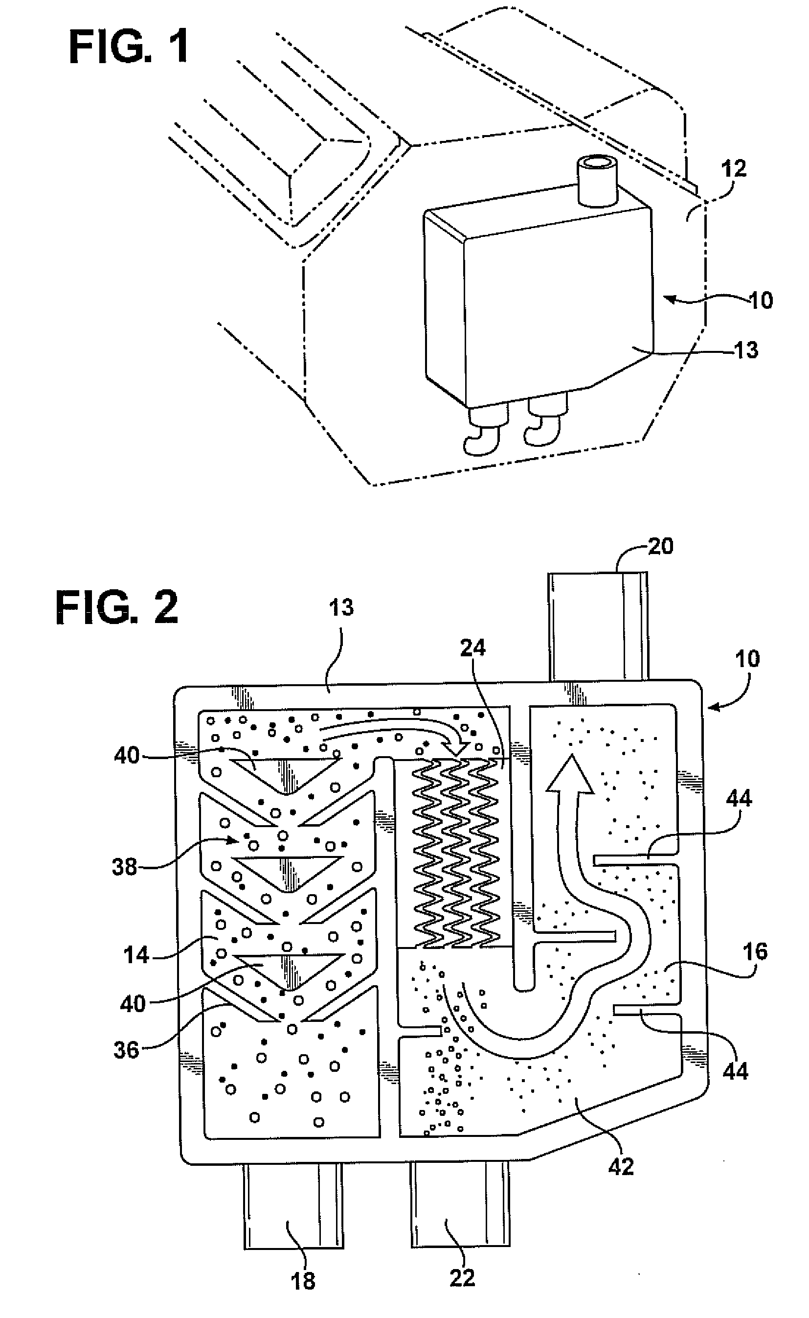
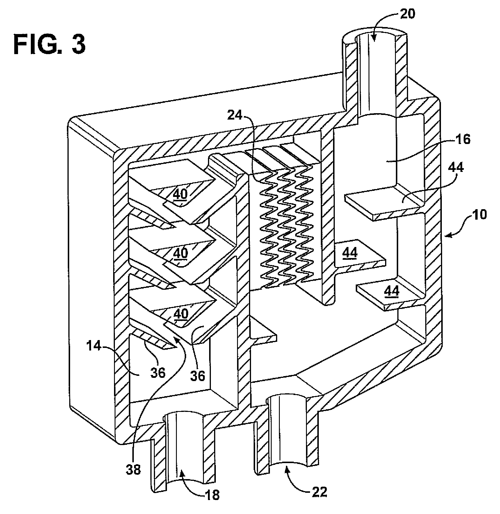
[0011]Referring to the Figures, wherein like numerals indicate corresponding parts throughout the several views, an oil separating device 10 for separating oil from crankcase gases is generally indicated at 10. With reference now to FIG. 1, the oil separating device 10 is part of the vehicle's PCV system and is mounted to the engine 12 so as to receive crankcase gases from the engine 12 and return filtered crankcase gases to the engine intake. The oil separating device 10 includes a housing having a first chamber 14 in communication with a second chamber 16, an inlet 18, an outlet 20 and an oil drain 22. The inlet 18 interconnects the engine 12 with the first chamber 14 so as to allow crankcase gases to be drawn into the first chamber 14. Crankcase gases may be drawn using a vacuum created in the manifold or by escaping exhaust gases, or may be manually drawn using a motor or the like. The outlet 20 interconnects the second chamber 16 with the engine 12 intake so as to allow crankca...


PUM

PropertyMeasurementUnit
lengthaaaaaaaaaa
lengthaaaaaaaaaa
pressureaaaaaaaaaa

Abstract

An oil separating device for separating micron and sub-micron particles of oil from crankcase gases is provided. The oil separating device includes a housing having a first chamber in communication with a second chamber, and a narrow wave-shaped passage disposed between the first chamber and the second chamber. The narrow wave-shaped passage is defined by a first inner wall having a first undulating surface opposite and spaced apart from a second inner wall having a second undulating surface mirroring the first undulating surface. The narrow wave-shaped passage is disposed downstream of the first chamber and above the oil drain so as to allow oil particles in crankcase gases passing from the inlet to the outlet to accumulate on the first and second inner walls and assist gravity in forcing the accumulated oil through the narrow wave-shaped passage into the oil drain.

Description

FIELD OF THE INVENTION[0001]The invention relates to an oil separating device for separating oil from crankcase gases. More particularly, the invention relates to an oil separating device having a narrow wave-shape passage downstream of a first chamber such that crankcase gases are drawn through the passage in the same direction in which separated oil drains.BACKGROUND OF THE INVENTION[0002]An internal combustion engine includes a combustion chamber, where a fuel air mixture is burned to cause movement of a set of reciprocating pistons, and a crankcase, which contains the crankshaft driven by the pistons. During operation, it is normal for the engine to experience “blow-by,” wherein combusted crankcase gases leak past the piston-cylinder gap from the combustion chamber and into the crankcase. These blow-by or crankcase gases contain moisture, acids and other undesired by-products of the combustion process.[0003]It is normal for crankcase gases to also include a very fine oil mist. T...

Claims


Application Information

Patent Timeline
Patent Type & Authority Applications(United States)
IPC IPC(8): F01M13/04B01D19/00
CPCF01M13/04F01M2013/0461F01M2013/0433F01M2013/0072
Inventor SHIEH, TENGHUA TOMNOMURA, SHOHEI
Owner TOYOTA MOTOR CO LTD
Why Eureka
Try Eureka