
V-belt type continously variable transmission

a technology of continuously variable transmission and belt type, which is applied in the direction of cycle, jet propulsion mounting, gearing, etc., can solve the problems of complicated manufacturing of belt type and difficulty in assembly to the power transmission cas

Active Publication Date: 2005-05-26
HONDA MOTOR CO LTD
View PDF8 Cites 52 Cited by
  • Summary
  • Abstract
  • Description
  • Claims
  • Application Information

AI Technical Summary

Benefits of technology

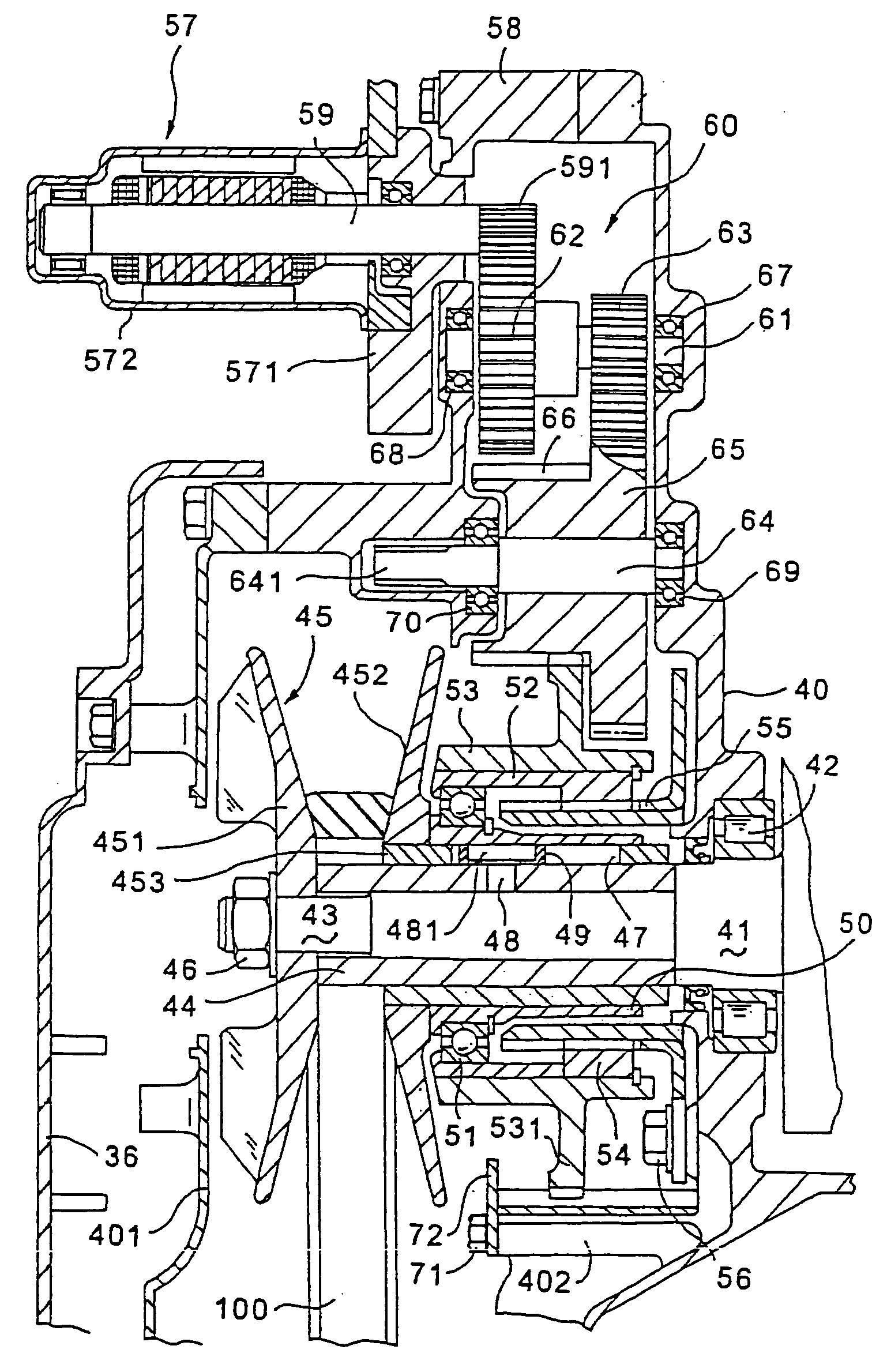
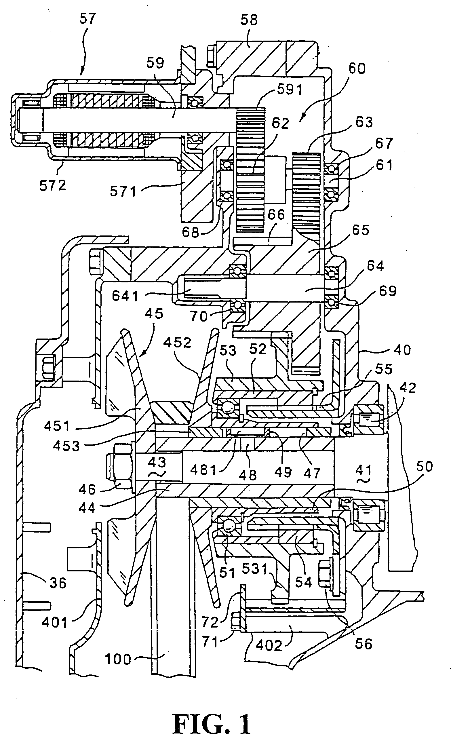
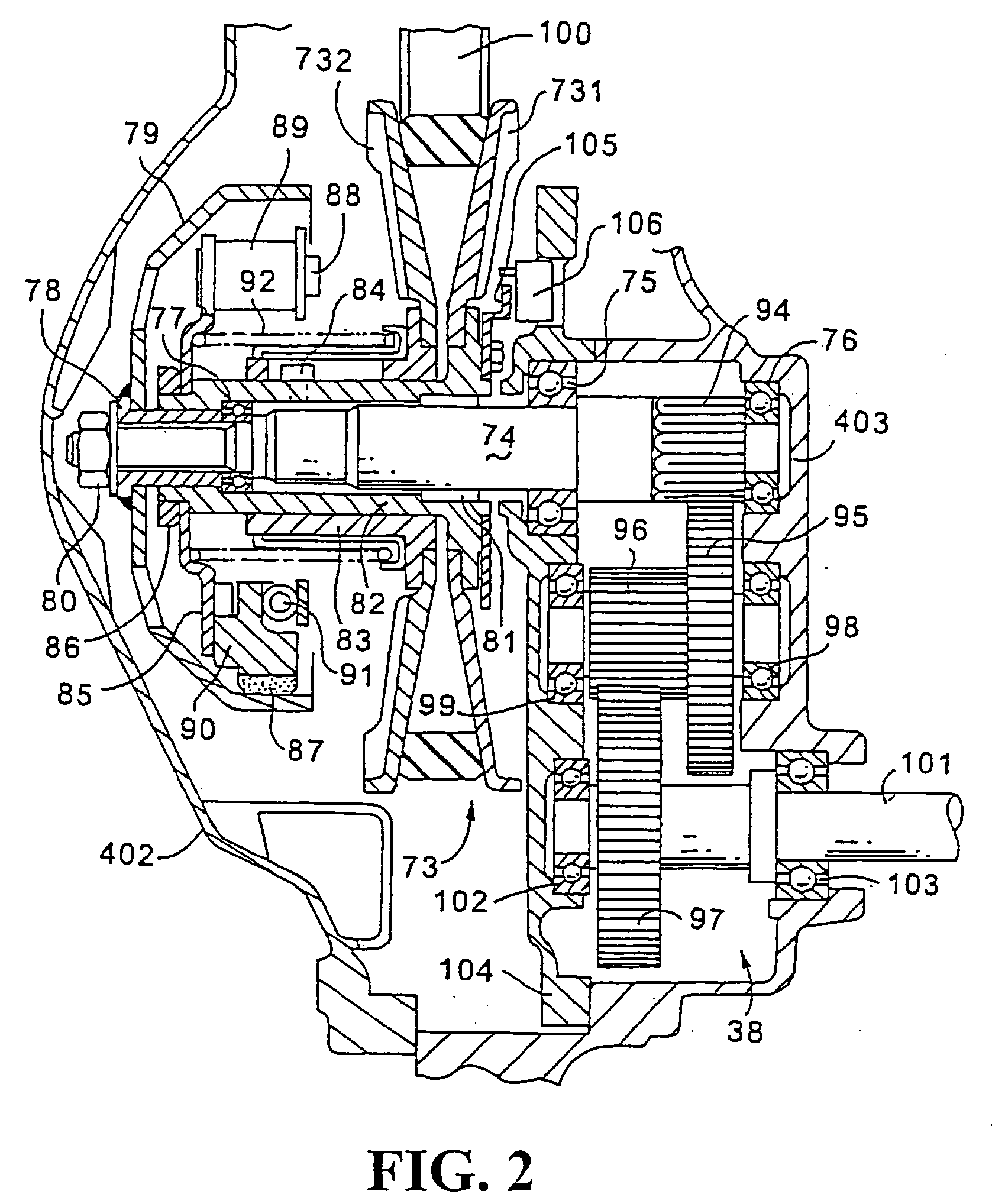
[0018] As a result of the first aspect of the invention as described above, the actuator cover which covers the motor and the gear system for driving the driving part of the driving pulley of the transmission apparatus is formed as a separate member from the power transmission case cover which covers the belt apparatus which is the body of the transmission apparatus. Accordingly, manufacture of molds for use for manufacture of the covers is facilitated, and also the workability when the covers are assembled to or disassembled from the power transmission case is good.
[0019] According to the second aspect of the invention, since also the water pump can be covered simultaneously, the maintenance is easy.
[0021] According to the fourth aspect of the invention, the disposition of the actuator at a position lower than the passenger steps contributes to making the center of gravity of the scooter type vehicle at a lower position.
[0023] According to the sixth aspect of the invention, the actuator can be protected further effectively by the support frame of a high rigidity.

Problems solved by technology

However, in order to form the power transmission case cover in such a manner as to cover the gear system and the motor, a complicated configuration must be formed integrally.
To this end, the mold for manufacture is obliged to be complicated, and also assembly to the power transmission case is not easy.

Method used


Image

  • V-belt type continously variable transmission
  • V-belt type continously variable transmission
  • V-belt type continously variable transmission

Examples


Embodiment Construction

[0040] In the following, an embodiment of the present invention is described with reference to the drawings. FIG. 3 is a side elevational view of an appearance of a scooter type motorcycle with a continuously variable transmission according to an embodiment of the present invention. Referring to FIG. 3, a vehicle body front portion 2 and a vehicle body rear portion 3 of a scooter type motorcycle 1 are connected to each other through a floor portion 4. The skeleton of the vehicle body is formed from a down tube 6 and a main tube 7 extending rearwardly upwardly from the down tube 6. A seat 8 is disposed above the main tube 7. An accommodation box for a helmet and a fuel tank (both not shown) are provided between the seat 8 and the main tube 7. The seat 8 serves also as a lid for the accommodation box.

[0041] The down tube 6 is joined at a front end thereto to a head pipe 5 provided on the vehicle body front portion 2. A front fork 12 is supported for pivotal motion on the head pipe 5....


PUM


Abstract

A belt continuously variable transmission apparatus having a case which includes a power transmission case (which is part of a crankcase of an engine), a power transmission case cover, and an actuator cover assembled forwardly of the power transmission case cover (displaced forwardly on a vehicle body). The actuator cover is formed as a separate member from the power transmission case cover, and supports a motor for driving a movable part of a driving pulley. In addition, the actuator cover covers a gear system. The actuator cover is integrated with a cover of the water pump. The resulting configuration improves the assembling of the actuator cover of the belt continuously variable transmission apparatus.

Description

CROSS-REFERENCE TO RELATED APPLICATION [0001] The present application is related to Japanese Patent Application No. 2003-342367 filed on Sep. 30, 2003, and Japanese Patent Application No. 2003-352965 filed on Oct. 10, 2003, the entire contents of which are hereby incorporated by reference. BACKGROUND OF THE INVENTION [0002] 1. Field of the Invention [0003] This invention relates to a belt-type continuously variable transmission apparatus, and more particularly to a V-belt continuously variable transmission apparatus wherein the transmission gear ratio can be controlled by an electric actuator. [0004] 2. Description of Background Art [0005] A V-belt continuously variable transmission apparatus is known wherein a V-belt extends between and around a driving pulley connected to a prime mover such as an engine and a driven pulley connected to a load and the wrapping diameters of the V-belt on the driving pulley and the driven pulley are varied continuously to control the transmission gea...

Claims


Application Information

Patent Timeline
IPC IPC(8): F16H9/18F16H57/02F16H63/06
CPCF16H9/18F16H57/02Y10T74/2186F16H2057/0203F16H2057/02065F16H63/062
Inventor ISHIKAWA, HIDEOOKI, KENJIASUMI, MICHIOKAMEMIZU, FUMINORIKOMURO, HIROKAZUSAKAMOTO, JUNICHI
Owner HONDA MOTOR CO LTD
Learn More