Motorized tracking device

a motorized tracking and motor technology, applied in the field of tracking systems, can solve the problems of reducing the torque and power requirements of the motor, and neither of these adjustments are in response, and achieve the effect of convenient and rapid interchange, easy and quick secured

Inactive Publication Date: 2009-02-12
STANEY WAYNE
View PDF26 Cites 2 Cited by
  • Summary
  • Abstract
  • Description
  • Claims
  • Application Information

AI Technical Summary

Benefits of technology

[0011]It is a further objective of the instant invention to provide a mounting and tracking support to which a solar panel array or antennae may be easily and quickly secured.
[0012]It is yet another objective of the instant invention to provide a mounting and tracking support wherein the components of the tracking system can be easily and rapidly interch...

Problems solved by technology

This also reduces the torque and power requirements of the motors since they are not able to withstand signi...

Method used


Image

  • Motorized tracking device
  • Motorized tracking device
  • Motorized tracking device

Examples


Embodiment Construction

[0024]While the present invention is susceptible of embodiment in various forms, there is shown in the drawings and will hereinafter be described a presently preferred embodiment with the understanding that the present disclosure is to be considered an exemplification of the invention and is not intended to limit the invention to the specific embodiments illustrated.

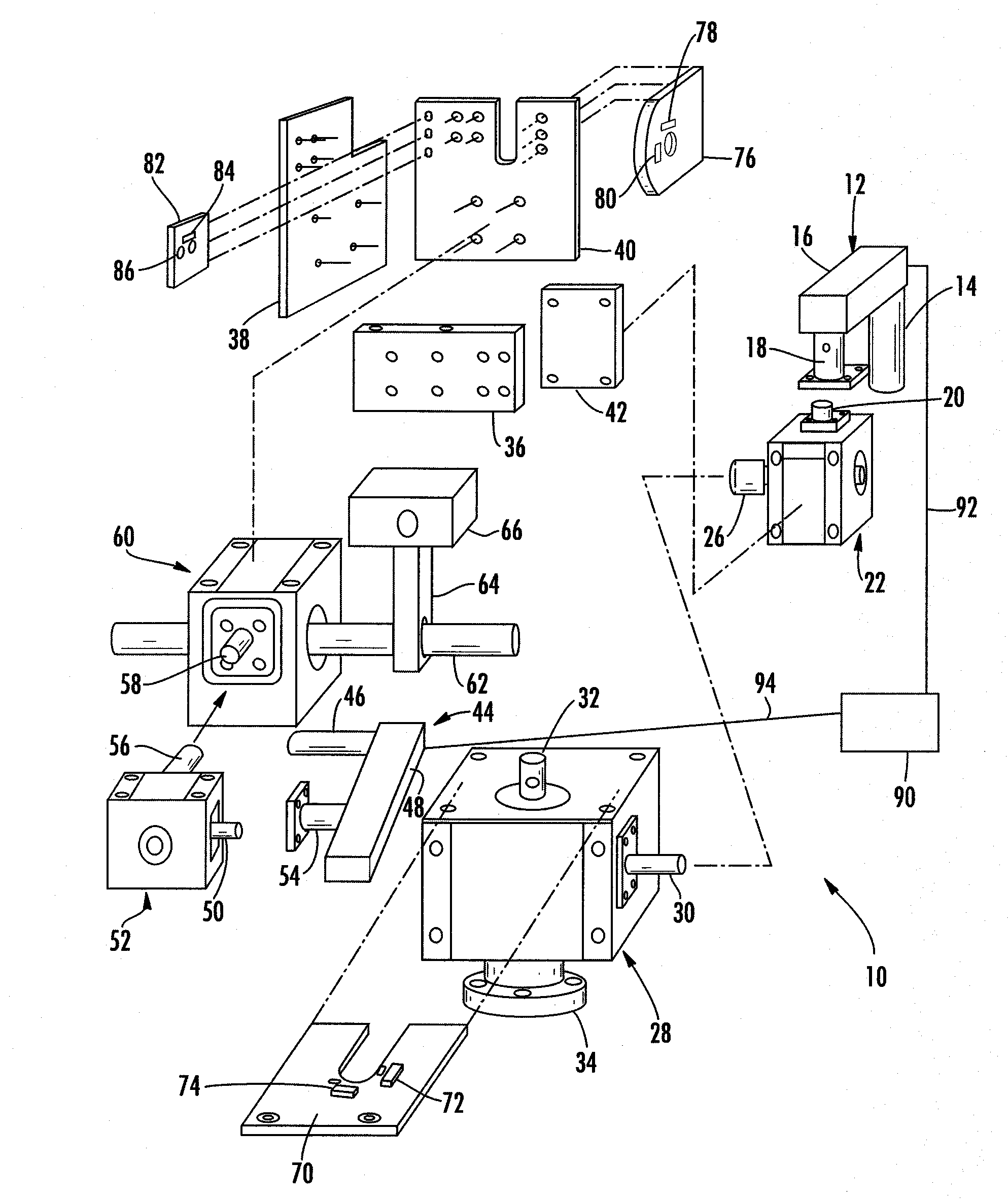
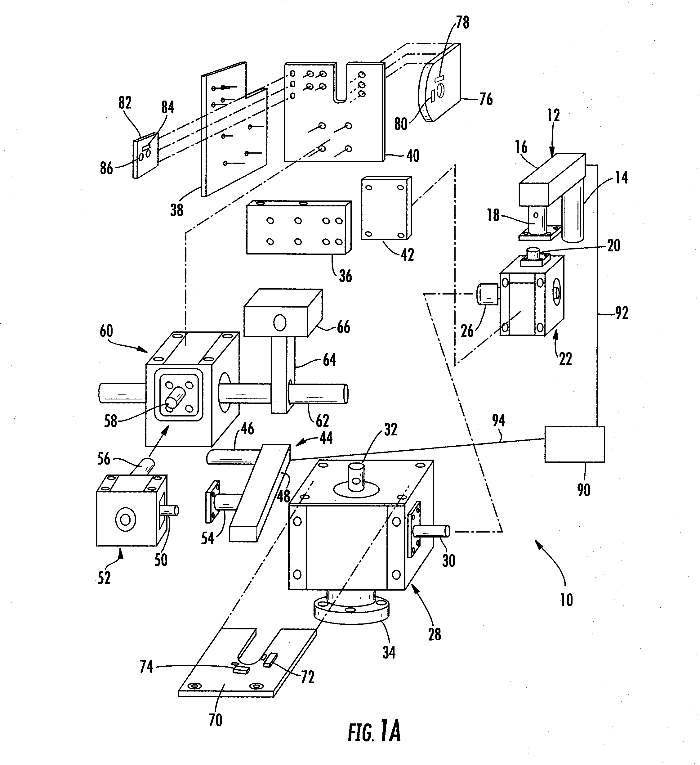
[0025]FIG. 1A is an exploded view of the tracking mechanism 10 for a solar panel or an antenna support. A first bi-directional actuator 12 can comprise a bi-directional electric motor 14, a motor control and gear assembly 16, and an output shaft. The output shaft is coupled to the input shaft 20 of a first small gear reducer drive 22. The actuator 12 is mounted to an actuator adaptor coupling 18 which surrounds the input shaft of the first small gear reducer drive. The coupling 18 is fixedly mounted to the housing of the first small gear reducer drive. This arrangement permits the actuator to be coupled to the input shaf...


PUM


Abstract

A mount and tracking mechanism for solar panels and antennae. The tracking mechanism comprises electric motor actuators which operate a small gear reducer drive. The output of the small reducer drive is connected to the input of a large gear reducer drive. The output of the large gear reducer drive moves the solar panels or antennae. This arrangement results in a substantial increase in the torque of the output shaft of the large gear reducer drive.

Description

CROSS-REFERENCE TO RELATED APPLICATIONS[0001]This application claims the benefit of U.S. Provisional Application Ser. No. 60 / 756,590, entitled “Motorized Tracking Device”, filed Jan. 4, 2006, which is hereby incorporated by reference.FIELD OF THE INVENTION[0002]The present invention relates to tracking systems and more specifically to systems which are useful in conjunction with a solar collector or a satellite antenna.BACKGROUND OF THE INVENTION[0003]Conventional tracking systems usually employ two independent drives to tilt the collector or antenna about two different axes. One axis is vertical and commonly called the azimuth. This tracks the sun or a satellite as it passes across the sky as a result of the earth's rotation. The other axis is the elevation axis wherein the collector or antenna is tilted within an angular range of about 90 degrees from the horizon upward. A typical day for a solar collector would start with the azimuth drive pointing east and end with it pointing w...

Claims


Application Information

Patent Timeline
IPC IPC(8): F24J2/38F24S50/20
CPCF24J2/38F24J2/542F24J2002/5437H01Q3/02Y02E10/47H01Q1/125F24S50/20F24S30/452F24S2030/11
Inventor STANEY, WAYNE
Owner STANEY WAYNE
Why Eureka
Try Eureka