

Cleaning apparatus, cleaning tank, cleaning method and computer-readable storage medium
- Summary
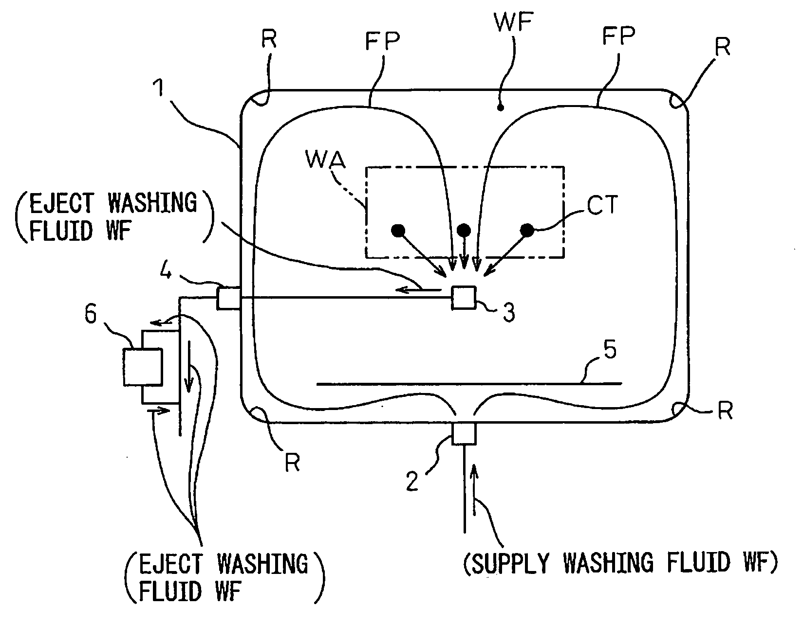
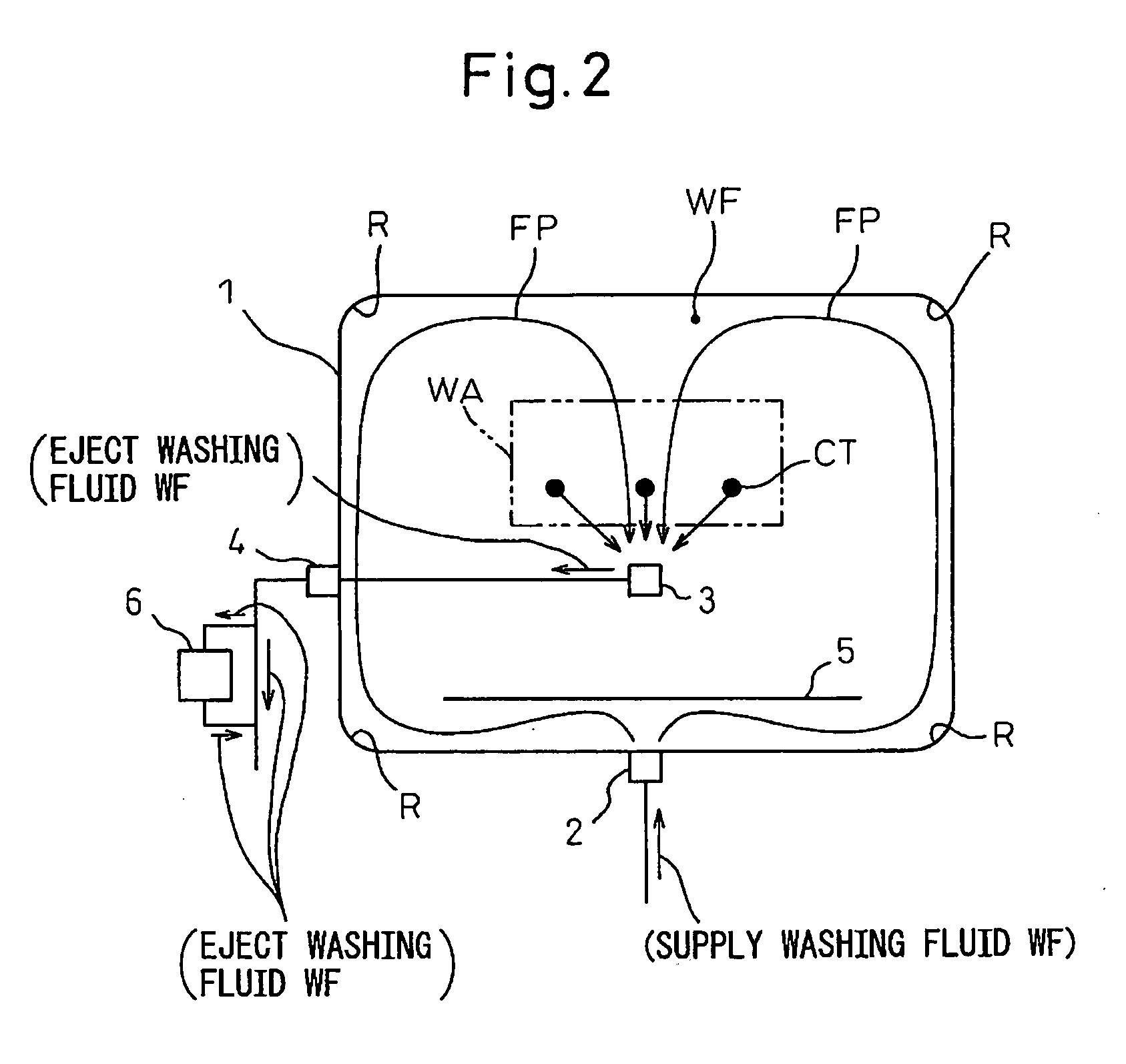
- Abstract
- Description
- Claims
- Application Information
AI Technical Summary
Benefits of technology
Problems solved by technology
Method used
Image

Examples
Embodiment Construction
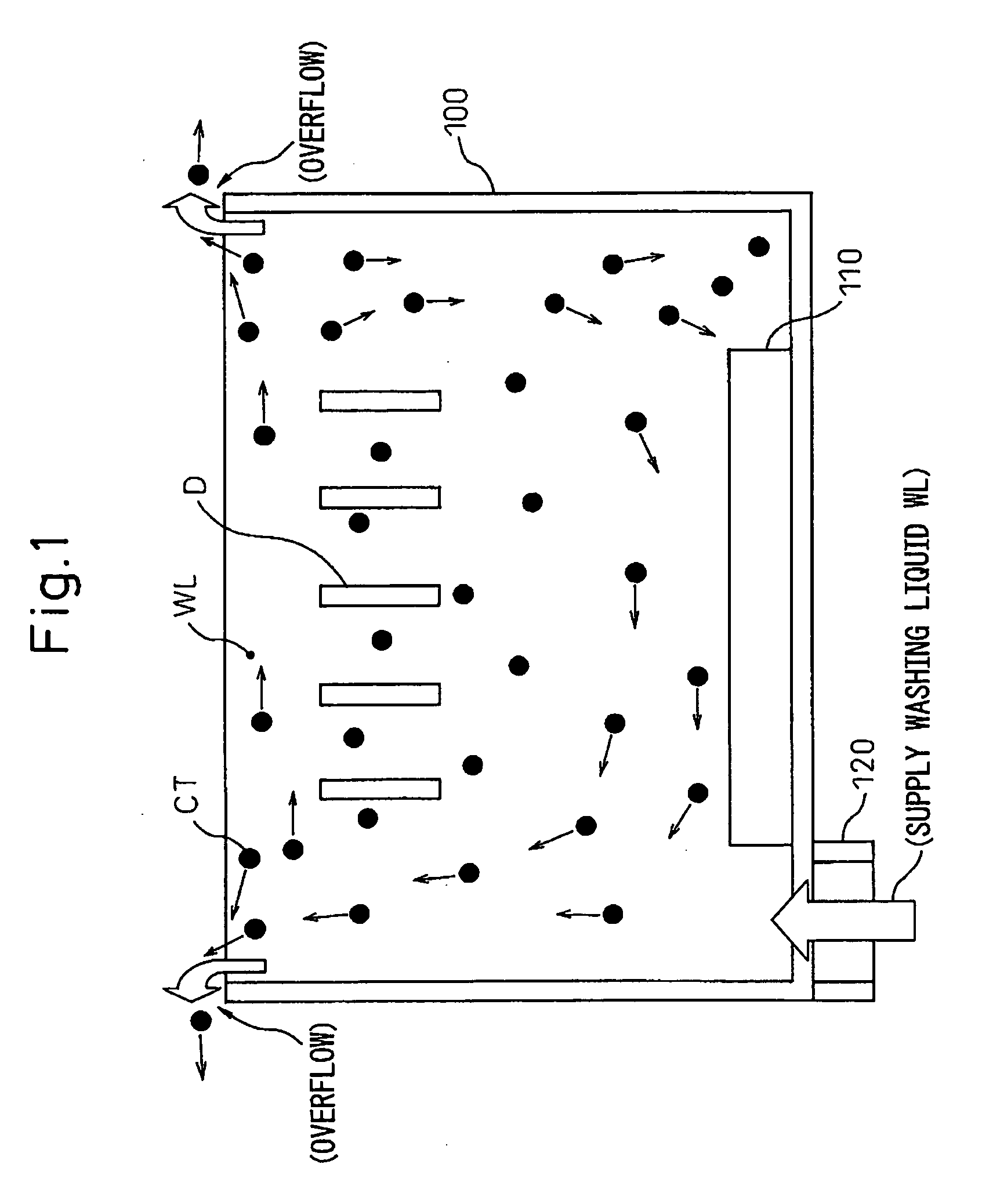
[0052]First, a conventional cleaning method and its problems will be described with reference to FIG. 1 before describing a cleaning apparatus, a cleaning tank and a cleaning method according to embodiments of the invention.
[0053]FIG. 1 is a lateral view of a cleaning tank for explaining a conventional cleaning method. As shown in FIG. 1, in the conventional cleaning method, a cleaning target D, such as a small-size device, is immersed in a washing liquid (or washing fluid) WL in a cleaning tank 100, and in this condition, ultrasonic waves are applied to the washing liquid WL by using an ultrasonic vibrator 110. Then, a contaminant (or contamination) CT on a surface of the cleaning target D is peeled off through a cavitation phenomenon. The washing liquid WL is supplied into the cleaning tank 100 through the supply hole 120 constantly, and the contaminant peeled off from the cleaning target is carried by the washing liquid flowing over the top face of the cleaning tank, and ejected ...
PUM
 Abstract
Description
Claims
Application Information