Peizoelectric generator particularly for use with wellbore drilling equipment

a generator and wellbore technology, applied in the field of wellbore drilling system and equipment, can solve the problems of each of the foregoing electric power supply devices and their own particular limitations

Inactive Publication Date: 2009-02-12
SCHLUMBERGER TECH CORP
View PDF12 Cites 37 Cited by
  • Summary
  • Abstract
  • Description
  • Claims
  • Application Information

AI Technical Summary

Problems solved by technology

Each of the foregoing electric power supplyin

Method used


Image

  • Peizoelectric generator particularly for use with wellbore drilling equipment
  • Peizoelectric generator particularly for use with wellbore drilling equipment
  • Peizoelectric generator particularly for use with wellbore drilling equipment

Examples


Embodiment Construction

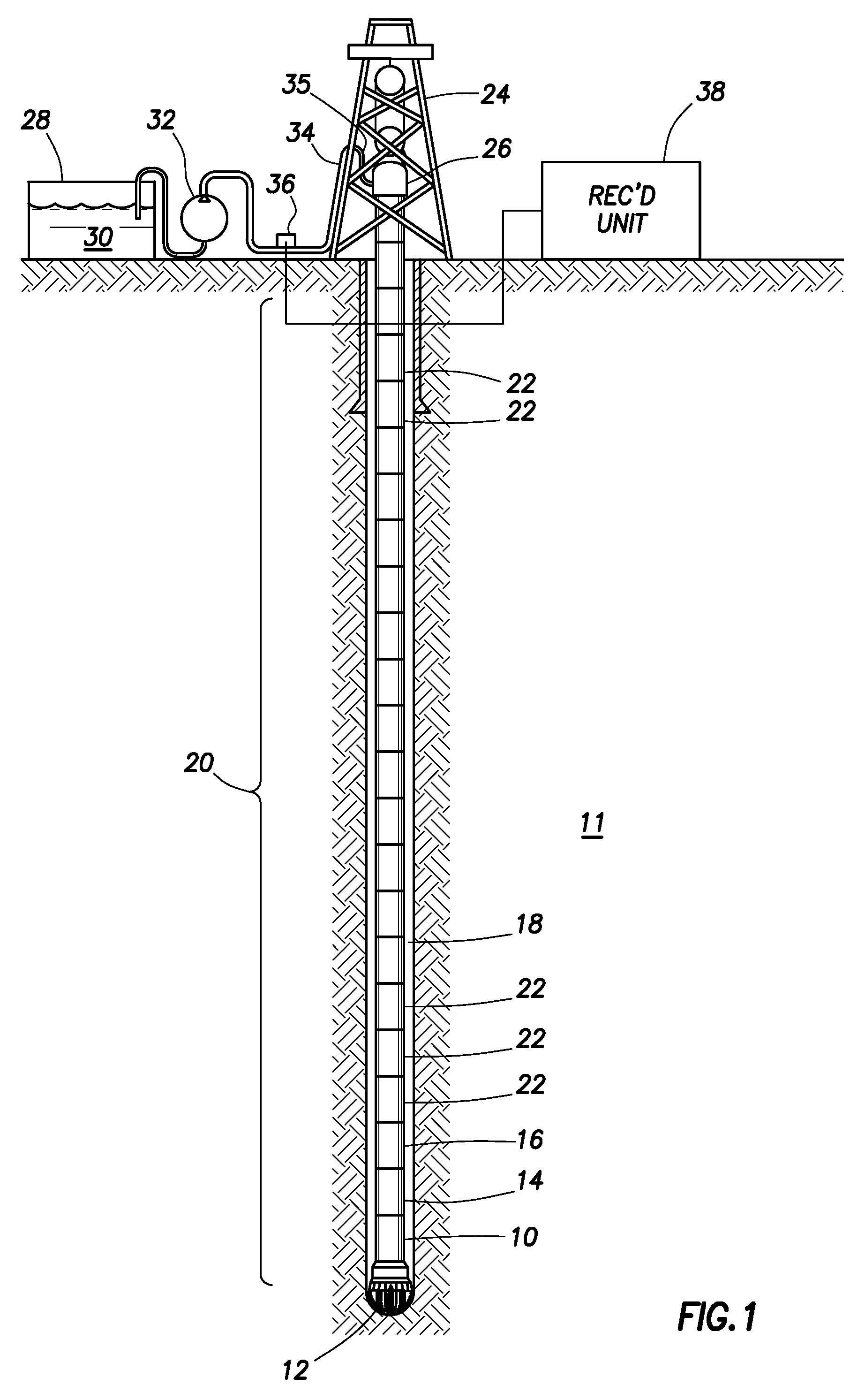
[0023]An example wellbore instrumentation system with which various implementations of the invention may be used is shown schematically in FIG. 1. The present example is described in terms of drilling instrumentation, however it should be understood that certain aspects of the invention have application in any wellbore system through which fluid is moved. Therefore, the invention is not limited in scope to drilling instrumentation.

[0024]In FIG. 1, a drilling rig 24 or similar lifting device suspends a conduit called a “drill string 20” within a wellbore 18 being drilled through subsurface Earth formations 11. The drill string 20 may be assembled by threadedly coupling together end to end a number of segments (“joints”) 22 of drill pipe. The drill string 20 may include a drill bit 12 at its lower end. When the drill bit 12 is axially urged into the formations 11 at the bottom of the wellbore 18 and when it is rotated by equipment (e.g., top drive 26) on the drilling rig 24, such urgi...


PUM


Abstract

An electric power generator includes a conduit disposed in a wellbore penetrating subsurface formations and at least one piezoelectric transducer in contact with the conduit. The piezoelectric transducer is configured to undergo stress in response to vibration in the conduit. The transducer includes a plurality of piezoelectric crystals stacked in a thickness direction and each polarized in the thickness direction. The transducer comprises at least one of a composite rubber layer disposed between successive piezoelectric crystals, and at least one support at a longitudinal end of the transducer configured to cause the crystals to bend in response to vibration in the conduit.

Description

CROSS-REFERENCE TO RELATED APPLICATIONS[0001]Not applicable.STATEMENT REGARDING FEDERALLY SPONSORED RESEARCH OR DEVELOPMENT[0002]Not applicable.BACKGROUND OF THE INVENTION[0003]1. Field of the Invention[0004]The invention relates generally to the field of wellbore drilling systems and equipment. More specifically, the invention relates to electric power generators used with wellbore drilling equipment.[0005]2. Background Art[0006]Wellbore-deployed equipment includes various devices coupled in a conduit called a “drill string” suspended in a wellbore for the drilling of such wellbore. A drill string is a length of pipe generally assembled from segments (“joints”) threadedly coupled end to end and having a drill bit at the lower end of the drill string. Drilling is performed by rotating and axially urging the drill bit to the bottom of the wellbore to extend the length of the wellbore.[0007]The foregoing devices can include measurement while drilling (“MWD”) and logging while drilling...

Claims


Application Information

Patent Timeline
IPC IPC(8): E21B47/12G08C19/00
CPCE21B17/003E21B41/0085H02N2/181H01L41/0833H02N2/186H10N30/503
Inventor GARCIA-OSUNA, FERNANDO
Owner SCHLUMBERGER TECH CORP
Why Eureka
Try Eureka