

Acoustic diaphragm and speaker
a diaphragm and oblique cone technology, applied in the direction of transducer diaphragms, electrical apparatus casings/cabinets/drawers, instruments, etc., can solve the problems of poor sound field expression, difficult to manufacture diaphragms of oblique cone type, and prone to standing wave, etc., to achieve excellent bass sound reproduction characteristics and enrich sound field expression
- Summary
- Abstract
- Description
- Claims
- Application Information
AI Technical Summary
Benefits of technology
Problems solved by technology
Method used
Image

Examples
first embodiment
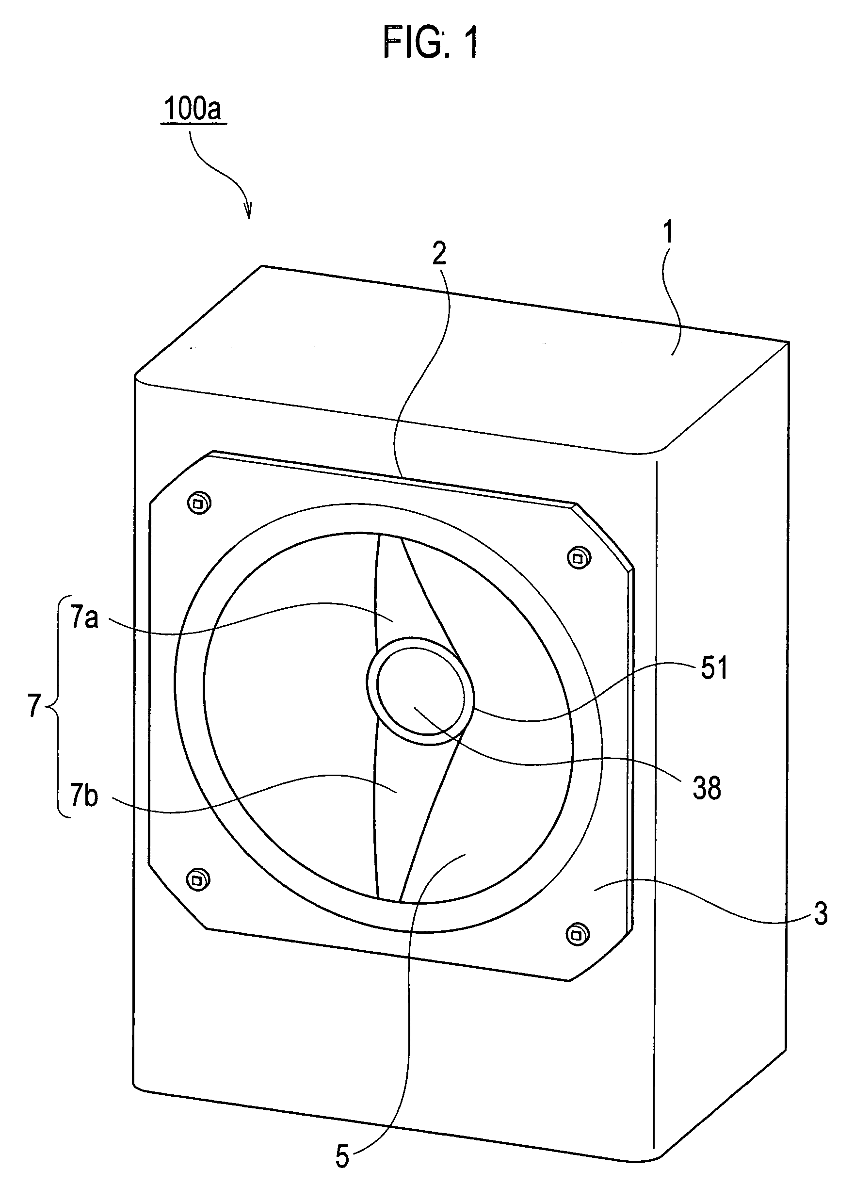
[0046]As shown in FIG. 1, a speaker 100a according to a first embodiment of the present invention includes: a cabinet 1 having a unit mounting opening 2 on a front surface thereof; and a speaker unit 3 mounted on the unit mounting opening 2.
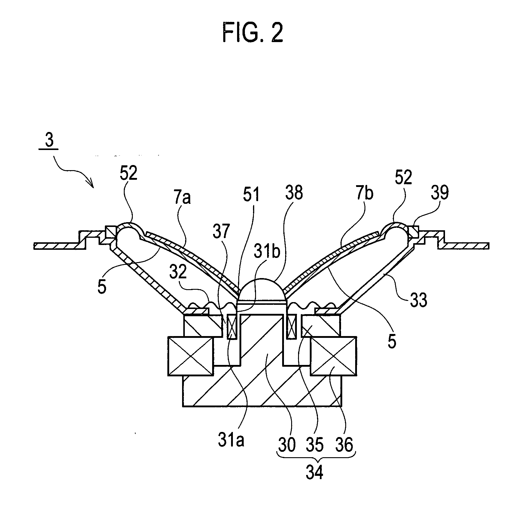
[0047]For example, as shown in FIG. 2, the speaker unit 3 includes: a magnetic circuit 34; a frame 33 disposed on the magnetic circuit 34; and a diaphragm 5 fixed to the frame 33. The magnetic circuit 34 includes: a doughnut-like plate 35; a doughnut-like magnet 36 provided under the plate 35; and a pole piece 30. A voice coil 31a is movably inserted into a magnetic gap 37 between the plate 35 and the pole piece 30. A damper 32 is adhered onto a voice coil bobbin 31b and the frame 33.
[0048]The diaphragm 5 is formed of a uniform material (isotropic material). The “uniform material” refers to a single material in which a sound propagation speed is substantially equal in every direction in the diaphragm. As the uniform material, for example, there a...
second embodiment
[0059]As shown in FIG. 7, a speaker 100b according to a second embodiment of the present invention is different from the speaker 100a shown in FIG. 1 in that the standing wave suppression members 7a and 7b are arranged in a substantially horizontal direction (that is, in a left and right direction of a page space of FIG. 7) with respect to the bottom surface of the cabinet 1.
[0060]The diaphragm 5 is formed of the uniform material (isotropic material). The “uniform material” in FIG. 7 refers to the single material in which the sound propagation speed is substantially equal in every direction in the diaphragm. As the uniform material, for example, the paper such as the pulp, the plastics such as the polypropylene, the metal such as the aluminum, and the like are usable.
[0061]It is preferable that a thickness of the standing wave suppression members 7a and 7b shown in FIG. 7 be set, for example, within the range of 10 μm to 700 μm in consideration for a relationship between the thickne...
third embodiment
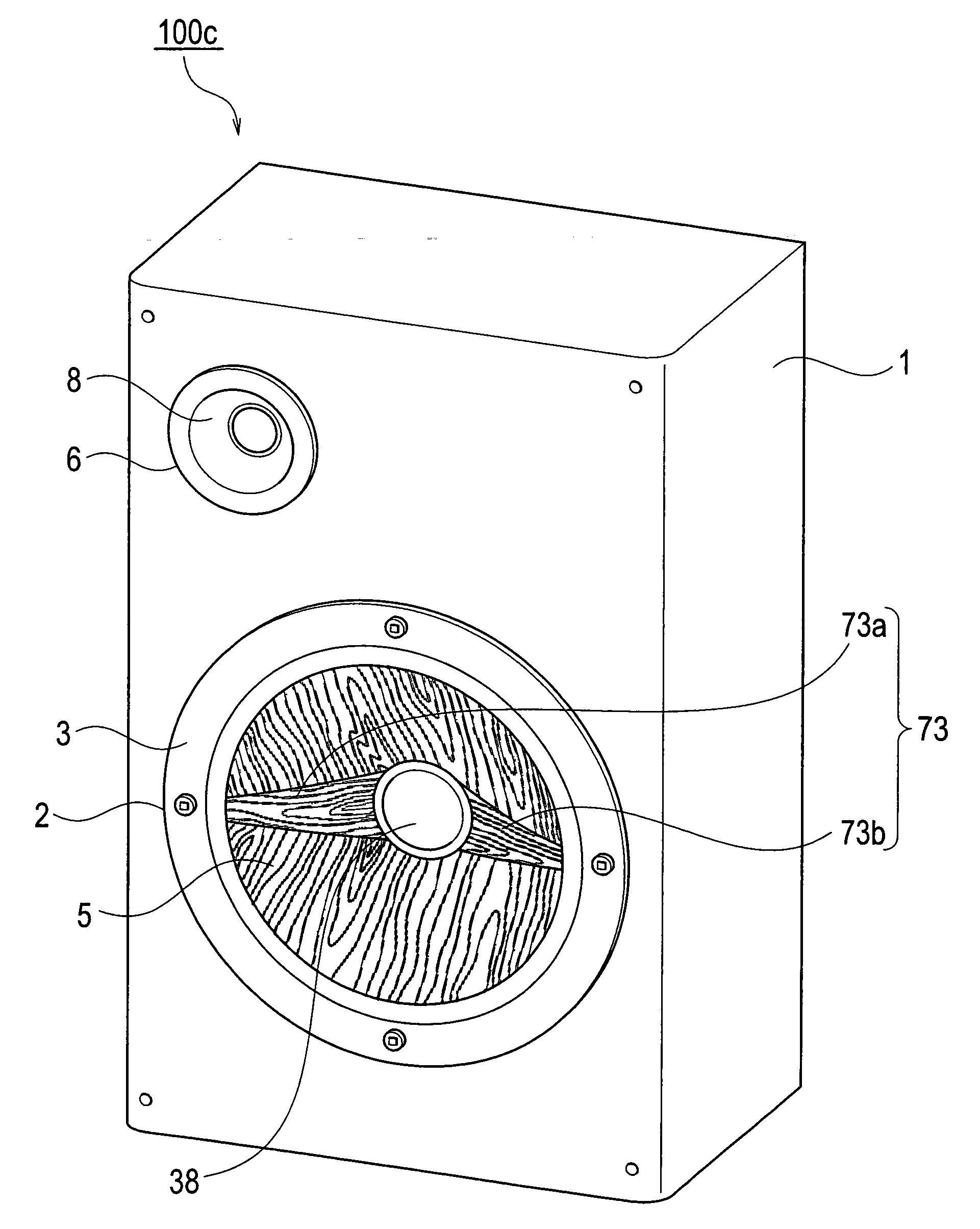
[0067]As shown in FIG. 9, a speaker 100c according to a third embodiment of the present invention includes: a cabinet 1 having the unit mounting opening 2 and a tweeter mounting opening 6 on a front surface thereof; the speaker unit 3 mounted on the unit mounting opening 2; and a tweeter 8 mounted on the tweeter mounting opening 6. The tweeter 8 is not essential.
[0068]A diaphragm 5 in FIG. 9 is made of wood, and is mounted on the unit mounting opening 2 so that a fiber direction thereof can go along with a direction perpendicular to the bottom surface of the cabinet 1 (that is, in an up and down direction of a page space of FIG. 9). As the wood for use in the diaphragm 5, natural wood is preferable, which satisfies the following respective conditions: for example, that it is easy to form a wooden sheet, that good acoustic characteristics are inherent, and so on in addition to that a vessel density is uniform and small, that the vessels are short, that wood fiber is long, that growth...
PUM
 Abstract
Description
Claims
Application Information